20
ModCon®75 Touch
Chapter 4,
ModCon75 Touch CPU Module
•
The CPU cannot operate independently. It must be plugged into the
back of an HMI panel. The HMI panel provides the CPU’s power
source.
Features:
•
IO/COM Bus connector for interfacing I/O modules
•
Isolated RS485.
•
Backup battery.
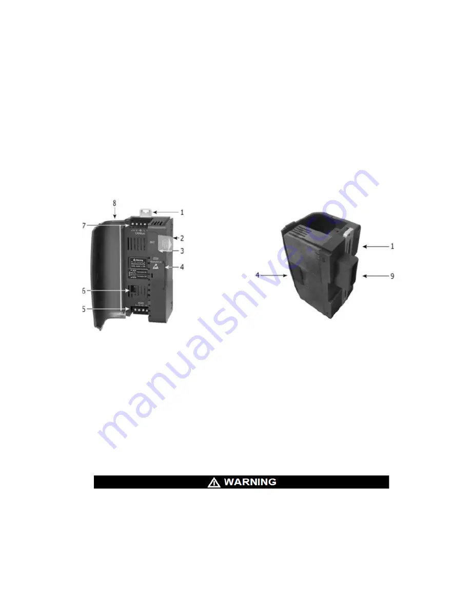
CPU Diagram
Figure 8. CPU Front and Rear View
1. DIN-rail clips
2. Battery pull-tab (remove during installation)
3. Battery compartment cover
4. IO/COM Bus connector, Shipped covered. Leave covered when not in use.
5. RS485 connector
6. RS485 termination selection DIP switch
7. CANbus connector-
Not Supported, No Customer Connection
8. CPU door
9. CPU connector to HMI panel
Installation
•
Disconnect system power before connecting or disconnecting any modules.
•
Components in this system are electrostatic discharge sensitive (ESDS). Use proper
personal grounding procedures when removing, handling or adjusting the electronic
modules.
FAILURE TO FOLLOW THE THESE WARNINGS CAN RESULT IN SERIOUS
PERSONAL INJURY OR LOSS OF LIFE.
Содержание ModCon 75
Страница 15: ...14 ModCon 75 Touch Figure 5 HMI Panel Mounting...
Страница 34: ...33 ModCon 75 Touch Figure 19 HMI Power Supply Connection 0V V 24VDC Figure 20 I O Power Supply Connection...
Страница 60: ...59 ModCon 75 Touch Dimensions Figure 58 Dimensions Front Figure 59 Dimensions Side...
Страница 61: ...60 ModCon 75 Touch Figure 60 Dimensions Top HMI I O Module CPU Module...
Страница 83: ...82 ModCon 75 Touch Figure B 8 Remote Relay Panel Mounting Figure B 9 Remote Relay Panel Mounted...


