ioLogik 2500 Series
Installation
2-7
Daisy-Chaining for I/O Expansion
Up to 8 ioLogik E1200 devices can be connected in a daisy chain configuration to the ioLogik 2500 via the
L1/Slave port on the ioLogik 2500. An IOxpress configuration scheme is called a project. If the IOxpress
project includes expansion devices, the ioLogik 2500 will automatically start running in expansion mode.
If the ioLogik 2500 is running, you can replace one of the expansion units without powering down the
ioLogik 2500. Take the following steps to replace an expansion unit:
1.
Power-off the expansion unit.
2.
Replace the unit with another expansion unit of the same model.
3.
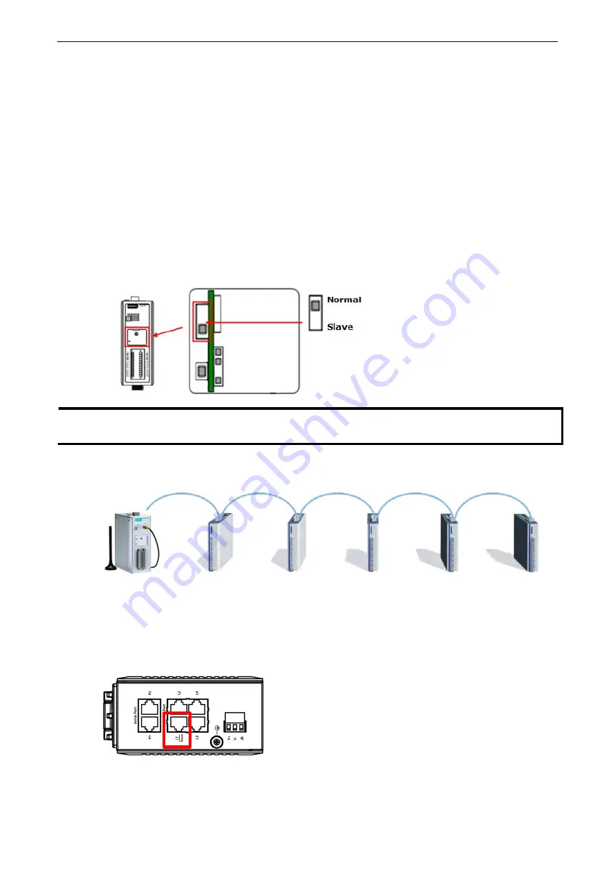
Access the DIP switch beneath the cover plate (as shown below).
4.
Move the DIP switch from the down position to the up position to trigger the ioLogik 2500 to refresh its
connection with the expansion units. If the DIP switch is already in the up position, move it down and
then back up again.
5.
The expansion unit will start running.
NOTE
Expansion units must be replaced with the same model of expansion unit. If you would like to use a
different expansion unit model, you must first change the relevant IOxpress settings.
The following figure illustrates a simple daisy-chain of I/O modules using the ioLogik 2500 for wireless
connectivity.
ioLogik 2500
ioLogik E1200
ioLogik E1200
ioLogik E1200
ioLogik E1200
ioLogik E1200
When daisy-chaining an array of devices, the first device in the chain (after the ioLogik 2500) must be
connected to the L1 Slave port on the top of the ioLogik 2500 (outlined in red in the diagram).
When a network failure occurs between the ioLogik 2500 and expansion I/O units, the ioLogik 2500’s auto-
recovery mechanism will reestablish a connection once the network is back up and running.


