15
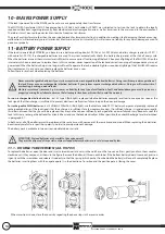
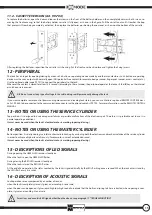
11.2 - CASSETTE VERSION (Art. 99.704)
To replace the batteries, open the door and loosen the screws on the front of the battery holder and then completely unscrew both screws, re-
moving the front covering, so that the battery holder cassette is fully open, as shown in the figure. Pull the cassette out until it reaches the stop
that prevents it from being completely extracted, then replace the batteries, positioning the new ones as shown on the bottom of the cassette.
After replacing the batteries, reposition the cassette in its housing. Put the front cover back in place and tighten the fixing screws.
12 - PERIPHERAL
The lock has an input for opening/closing by means of a button or operating device made by another manufacturer. Such button or operating
device must have an output with normally open (NO) potential-free contact (for example: badge scanner, fingerprint scanner, access control, etc.).
Use the optional cable (code 99.701) to connect the peripheral to the lock.
Whenever the contact is closed for at least 0.5 seconds (according to the set mode), the peripheral operates the lock as if the (
E
) key on the internal
escutcheon were pressed.
If you want complete remote control (commanding movements and reading lock status), you can use Mottura’s optional REMOTE CONTROL devi-
ce Art. 99.684, to be connected to the communication connector with optional cable Art. 99.702. For more information, see the REMOTE CONTROL
MANUAL.
N.B. Do not connect any type of voltage to the cable: doing so will permanently damage the lock.
13 - NOTES ON USING THE SERVICE CYLINDER
14 - NOTES ON USING THE MASTER CYLINDER
Top position. It is designed to overcome power failures or possible malfunctions of the electronic part. Therefore, it is preferable not to use it in
normal operating conditions.
It must never be used when the lock’s electrical motor is working (opening/closing).
Bottom position. It is designed to give total mechanical interlocking by excluding both the electronic and mechanical drive of the service cylinder
in order to achieve a higher level of security (for example, in case of extended absence).
It must never be used when the lock’s electrical motor is working (opening/closing).
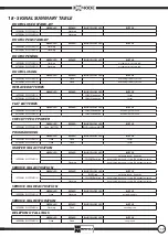
15 - DESCRIPTIONS OF LED SIGNALS
16 - DESCRIPTION OF ACOUSTIC SIGNALS
During opening the GREEN LED remains steadily on.
When the lock is open the GREEN LED flashes.
During closing the RED LED remains steadily on.
When the lock is closed the RED LED flashes.
At the end of an operation, the status reached by the lock is signaled briefly by the LEDs flashing once a second. When the lock enters stand-by
the LEDs flash every 4 seconds.
Lock operations are accompanied by a number of sounds:
when the lock is completely closed, it gives a descending 3-tone scale,
when the door can be opened, it gives rapid high-low-high sound to indicate that the bolts and spring latch are retracted, when opening is com-
plete, it gives an ascending 3-tone scale.
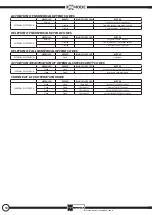
For actions and acoustic/LED signals other than the above, see paragraph 17 “TROUBLESHOOTING.”
Содержание Xmode F1.0
Страница 19: ...19 NOTE ...
Страница 20: ...99286GB 06 14 a_013334 SAFEGUARDINGYOUR SECURITY www mottura it ...


