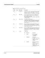


Obtaining Results from the Power-On Self-Test
Firmware
4 - 24
PPC/PMC-8260/DS1
Obtaining Results from the Power-On Self-Test
While the POST is running, the firmware stores the results of each test in the dual-
ported RAM of the PowerQUICC II. Progress is indicated via:
•
Front panel LEDs (see the “LED States During Power Up” section page 3-5)
•
Mailbox register 5 of the PowerSpan II (offset 464
16
, see section “POST
Result Storage Area” on page 4-24)
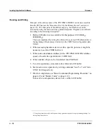
Since the POST does not halt if it detects errors your application software should
evaluate the POST results written into mailbox register 5 of the PowerSpan II as
soon as possible. Otherwise, a fatal error while the POST is running will cause the
software watchdog timer to expire and reset the board.
Requirements
POST results are obtained via the primary booter. In order to evaluate the POST re-
sults, your driver has to include at least the programming routines for:
•
Starting the pimary booter
Program your software according to the description on page 4-33.
•
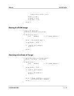
Reading and writing
Program your software according to the description on page 4-22.
•
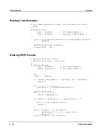
Reading POST results
For a code example, see page 4-38.
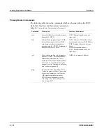
For information on the primary booter’s communication window, commands, pa-
rameters, and command programming conventions, refer to section “Primary
Booter” on page 4-15.
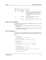
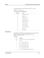
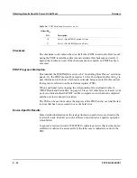
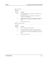
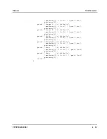
POST Result Storage Area
The POST stores information on its progress and the results in bank 12 of the inter-
nal dual-ported RAM of the PowerQUICC II. The offset relative to the IMMR is
B800
16
, resulting in the absolute address of F000B800
16
in the memory map of the
PPC/PMC-8260/DS1.
Содержание PPC/PMC-8260/DS1
Страница 1: ...PPC PMC 8260 DS1 Reference Guide P N 6806800B10A July 2006 ...
Страница 8: ...viii PPC PMC 8260 DS1 ...
Страница 22: ...xxii PPC PMC 8260 DS1 ...
Страница 26: ...xxvi PPC PMC 8260 DS1 ...
Страница 30: ...xxx PPC PMC 8260 DS1 ...
Страница 31: ...1 Introduction ...
Страница 32: ......
Страница 39: ...2 Installation ...
Страница 40: ......
Страница 53: ...3 Indicators and Connectors ...
Страница 54: ......
Страница 64: ...On Board Connectors Indicators and Connectors 3 12 PPC PMC 8260 DS1 ...
Страница 65: ...4 Firmware ...
Страница 66: ......
Страница 104: ...Code Examples Firmware 4 40 PPC PMC 8260 DS1 ...
Страница 105: ...5 Memory Map and Devices ...
Страница 106: ......
Страница 132: ...Resetting the Devices Memory Map and Devices 5 28 PPC PMC 8260 DS1 ...
Страница 133: ...6 TDM Channel Configuration ...
Страница 134: ......
Страница 145: ...A Troubleshooting ...
Страница 146: ......
Страница 148: ...A 4 PPC PMC 8260 DS1 ...
Страница 150: ...I 2 PPC PMC 8260 DS1 ...