


Firmware
Loading Application Software
PPC/PMC-8260/DS1
4 - 13
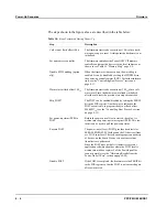
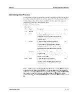
Controlling Boot Process
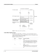
The execution of the power-up sequence can be controlled by the host via the driver
by setting configuration bits in the mailbox register #7 of the PowerSpan II PCI-to-
60x bus bridge (offset 46C
16
relative to BAR0). In this context, this register is
referred to as power-up control register (PCR).
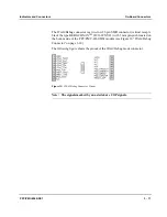
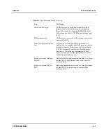
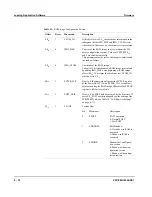
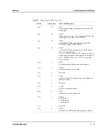
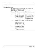
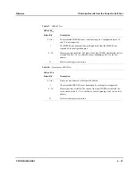
Table 12:
PCR Register Settings
Offset:
46C
16
Bit
Signal
Description
Access
31...4
Reserved
3
INI
1: Firmware is allowed to perform write accesses to
PowerSpan II PCI bridge.
In particular, it will provide progress information on
the boot process and enable access to the 60x bus
from the PCI bus.
r/w
2
WDDIS
0: Software watchdog timer remains enabled.
1: Software watchdog timer will be disabled.
It is not possible to enable the software watchdog
timer once it has been disabled except by resetting
PPC/PMC-8260/DS1. In any case, the firmware will
periodically trigger the software watchdog to prevent
it from expiring.
r/w
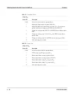
1
ROMSKIP
0: Firmware will look for a ROM image and execute
it if one is found.
1: Firmware will always execute primary booter and
not look for ROM image.
r/w
0 (lsb)
PSKIP
0: Power-on self-test will be executed.
1: Power-on self-test will not be executed.
This bit is set by the firmware before the power-on
self-test is started to prevent the POST from being
executed in future.
r/w
Note: Another way to control whether the firmware executes POST is to pro-
gram the byte at flash offset 000400F1
16
: If programmed to 0, the firmware
will never execute the POST. If it is programmed to FF
16
and the PCR[PSKIP]
bit is set to 1, the POST will not be executed either. If 000400F1
16
is pro-
grammed to FF
16
and the PCR[PSKIP] bit is set to 0, the POST will be execut-
ed.
Содержание PPC/PMC-8260/DS1
Страница 1: ...PPC PMC 8260 DS1 Reference Guide P N 6806800B10A July 2006 ...
Страница 8: ...viii PPC PMC 8260 DS1 ...
Страница 22: ...xxii PPC PMC 8260 DS1 ...
Страница 26: ...xxvi PPC PMC 8260 DS1 ...
Страница 30: ...xxx PPC PMC 8260 DS1 ...
Страница 31: ...1 Introduction ...
Страница 32: ......
Страница 39: ...2 Installation ...
Страница 40: ......
Страница 53: ...3 Indicators and Connectors ...
Страница 54: ......
Страница 64: ...On Board Connectors Indicators and Connectors 3 12 PPC PMC 8260 DS1 ...
Страница 65: ...4 Firmware ...
Страница 66: ......
Страница 104: ...Code Examples Firmware 4 40 PPC PMC 8260 DS1 ...
Страница 105: ...5 Memory Map and Devices ...
Страница 106: ......
Страница 132: ...Resetting the Devices Memory Map and Devices 5 28 PPC PMC 8260 DS1 ...
Страница 133: ...6 TDM Channel Configuration ...
Страница 134: ......
Страница 145: ...A Troubleshooting ...
Страница 146: ......
Страница 148: ...A 4 PPC PMC 8260 DS1 ...
Страница 150: ...I 2 PPC PMC 8260 DS1 ...