


Memory Map and Devices
PowerSPAN II PCI Bus Bridge
PPC/PMC-8260/DS1
5 - 13
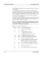
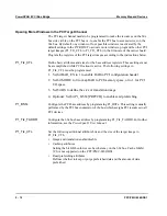
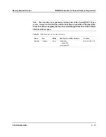
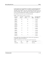
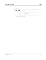
The following table shows an example of how to program the PCI Target Image#0.
For further information, refer to the
PowerSPAN II User Manual.
Table 26:
PCI Target Image#0 Programming Example
PowerSPAN II
Register
Register Contents
Comment
P1_TI0_CTL
E60A02C0
16
IMG_EN = 1: Image enabled
TA_EN = 1: Translation enabled
BAR_EN = 1: BAR enabled
1) Set via configuration E
2
PROM.
1)
MD_EN = 0: No master decode
BS = 616: 4 MByte size
2) Set via configuration E
2
PROM.
2)
MODE = 0: PCI memory space
RTT = 0A
16
GBL = 0: Ensure cache coherency
CI = 0: No cache inhibit
WTT = 02
16
PRKEEP = 1: Keep prefetched data
END = 10
2
: Big endian
MRA = 0: No aliasing
RD_AMT = 0: 8 byte prefetched.
P1_BST0
D0000008
16
PCI memory space address: D0000000
16
Read prefetching enabled
3) Set via configuration E
2
PROM.
3)
P1_TI0_TADDR
000000FE
16
60x bus base address: 00000000
16
Mx = 1: Claim transactions from all masters
P1_CSR
02B00006
16
MS = 1: Memory space enable
BM = 1: Bus master enable
With these settings, the PCI bus address range D0000000
16
to D0400000
16
corre-
sponds to the PPC/PMC-8260/DS1 60x bus address range 00000000
16
to
00400000
16
, which is the first 4 MByte of the SDRAM.
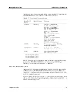
Accessible 60x Bus Resources
The PowerSPAN II can only perform 60x bus transfers with a port size of 64 bits.
For this reason only the SDRAM, the SSRAM and the dual-ported RAM of the
PowerQUICC II are accessible. All other devices on the 8-bit bus (E1/T1/J1 fram-
ers, T8105) cannot be accessed.
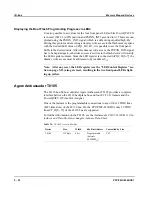
In order to update the firmware, it is possible to access the boot flash device and the
LED register. Refer to the “Programming the Boot Flash when PowerQUICC II is
in Reset” section on page 5-19.
Содержание PPC/PMC-8260/DS1
Страница 1: ...PPC PMC 8260 DS1 Reference Guide P N 6806800B10A July 2006 ...
Страница 8: ...viii PPC PMC 8260 DS1 ...
Страница 22: ...xxii PPC PMC 8260 DS1 ...
Страница 26: ...xxvi PPC PMC 8260 DS1 ...
Страница 30: ...xxx PPC PMC 8260 DS1 ...
Страница 31: ...1 Introduction ...
Страница 32: ......
Страница 39: ...2 Installation ...
Страница 40: ......
Страница 53: ...3 Indicators and Connectors ...
Страница 54: ......
Страница 64: ...On Board Connectors Indicators and Connectors 3 12 PPC PMC 8260 DS1 ...
Страница 65: ...4 Firmware ...
Страница 66: ......
Страница 104: ...Code Examples Firmware 4 40 PPC PMC 8260 DS1 ...
Страница 105: ...5 Memory Map and Devices ...
Страница 106: ......
Страница 132: ...Resetting the Devices Memory Map and Devices 5 28 PPC PMC 8260 DS1 ...
Страница 133: ...6 TDM Channel Configuration ...
Страница 134: ......
Страница 145: ...A Troubleshooting ...
Страница 146: ......
Страница 148: ...A 4 PPC PMC 8260 DS1 ...
Страница 150: ...I 2 PPC PMC 8260 DS1 ...