

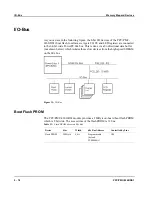


I/O-Bus
Memory Map and Devices
5 - 22
PPC/PMC-8260/DS1
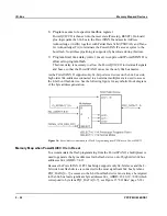
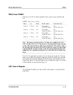
Displaying the Boot Flash Programming Progress via LEDs
It is also possible to set values for the four front panel LEDs while PowerQUICC II
is in reset (SW1-2 in ON position and PSPAN_INT5 asserted low). This is accom-
plished using the PSPAN_INT3 signal, which is a default input pulled high. By
driving this pin low and executing a dummy write access to the flash memory space
with the desired LED value on PQ2_D0...D7, it is possible to set the front panel
LEDs to the desired value. After this dummy write access, the PSPAN_INT3 signal
has to be negated again, otherwise successive writes to the flash device will modify
the LED register contents. Since the LED register is connected to PQ2_D[0...7], the
dummy write access must be addressed to byte address 0
16
.
Note: After any reset, the LED register (see the “LED Control Register” sec-
tion on page 5-23) also gets reset, resulting in the two front panel LEDs light-
ing up yellow.
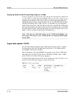
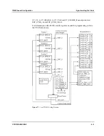
Agere Ambassador T8105
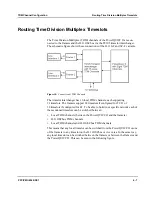
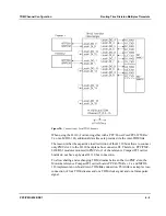
The H.110 bus/SCbus controller Agere Ambassador T8105 provides a complete
interface between the H.110 backplane bus and four E1/T1/J1 framers and the
PowerQUICC II Time Slot Assigner.
One of the features is the programmable connections to any of the 32 TDM lines
(4096 time slots) on the H.110 bus. On the PPC/PMC-8260/DS1 only 16 TDM
lines CT_D[0...15] of the H.110 bus are supported.
For further information on the T8105, see the
Ambassador T8105 H.100/H.110 In-
terfaces and Time-Slot Interchangers Advance Data Sheet
.
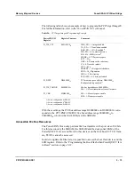
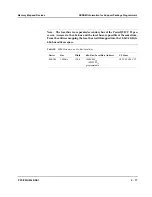
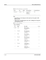
Table 34:
T8105 Access on 60x-Bus
Device
Size
Width
60x Bus Address
Controlled by Line
T8105
512 Byte
8 bit
Programmable
(default:
F0080000
16
)
CS7
Содержание PPC/PMC-8260/DS1
Страница 1: ...PPC PMC 8260 DS1 Reference Guide P N 6806800B10A July 2006 ...
Страница 8: ...viii PPC PMC 8260 DS1 ...
Страница 22: ...xxii PPC PMC 8260 DS1 ...
Страница 26: ...xxvi PPC PMC 8260 DS1 ...
Страница 30: ...xxx PPC PMC 8260 DS1 ...
Страница 31: ...1 Introduction ...
Страница 32: ......
Страница 39: ...2 Installation ...
Страница 40: ......
Страница 53: ...3 Indicators and Connectors ...
Страница 54: ......
Страница 64: ...On Board Connectors Indicators and Connectors 3 12 PPC PMC 8260 DS1 ...
Страница 65: ...4 Firmware ...
Страница 66: ......
Страница 104: ...Code Examples Firmware 4 40 PPC PMC 8260 DS1 ...
Страница 105: ...5 Memory Map and Devices ...
Страница 106: ......
Страница 132: ...Resetting the Devices Memory Map and Devices 5 28 PPC PMC 8260 DS1 ...
Страница 133: ...6 TDM Channel Configuration ...
Страница 134: ......
Страница 145: ...A Troubleshooting ...
Страница 146: ......
Страница 148: ...A 4 PPC PMC 8260 DS1 ...
Страница 150: ...I 2 PPC PMC 8260 DS1 ...