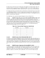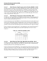
Enhanced Serial Audio Interface (ESAI)
ESAI Programming Model
MOTOROLA
DSP56367
10-35
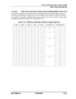
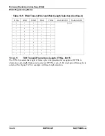
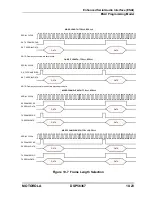
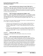
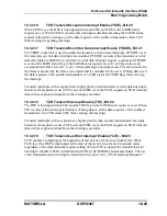
10.3.5
ESAI COMMON CONTROL REGISTER (SAICR)
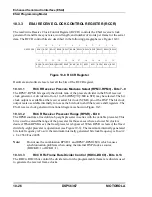
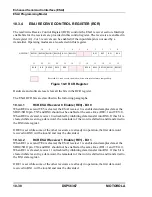
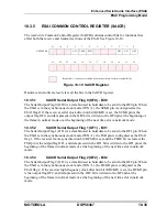
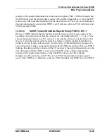
The read/write Common Control Register (SAICR) contains control bits for functions that
affect both the receive and transmit sections of the ESAI. See Figure 10-10.
Hardware and software reset clear all the bits in the SAICR register.
10.3.5.1
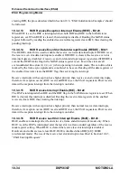
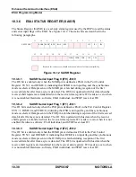
SAICR Serial Output Flag 0 (OF0) - Bit 0
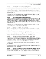
The Serial Output Flag 0 (OF0) is a data bit used to hold data to be send to the OF0 pin. When
the ESAI is in the synchronous clock mode (SYN=1), the SCKR pin is configured as the
ESAI flag 0. If the receiver serial clock direction bit (RCKD) is set, the SCKR pin is the
output flag OF0, and data present in the OF0 bit is written to the OF0 pin at the beginning of
the frame in normal mode or at the beginning of the next time slot in network mode.
10.3.5.2
SAICR Serial Output Flag 1 (OF1) - Bit 1
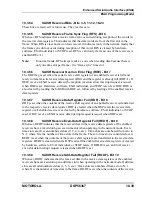
The Serial Output Flag 1 (OF1) is a data bit used to hold data to be send to the OF1 pin. When
the ESAI is in the synchronous clock mode (SYN=1), the FSR pin is configured as the ESAI
flag 1. If the receiver frame sync direction bit (RFSD) is set and the TEBE bit is cleared, the
FSR pin is the output flag OF1, and data present in the OF1 bit is written to the OF1 pin at the
beginning of the frame in normal mode or at the beginning of the next time slot in network
mode.
10.3.5.3
SAICR Serial Output Flag 2 (OF2) - Bit 2
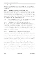
The Serial Output Flag 2 (OF2) is a data bit used to hold data to be send to the OF2 pin. When
the ESAI is in the synchronous clock mode (SYN=1), the HCKR pin is configured as the
ESAI flag 2. If the receiver high frequency clock direction bit (RHCKD) is set, the HCKR pin
is the output flag OF2, and data present in the OF2 bit is written to the OF2 pin at the
beginning of the frame in normal mode or at the beginning of the next time slot in network
mode.
11
10
9
8
7
6
5
4
3
2
1
0
X:$FFFFB4
ALC
TEBE
SYN
OF2
OF1
OF0
23
22
21
20
19
18
17
16
15
14
13
12
Reserved bit - read as zero; should be written with zero for future compatibility.
Figure 10-10 SAICR Register
Содержание DSP56367
Страница 16: ...xvi MOTOROLA CONTENTS Paragraph Number Title Page Number ...
Страница 22: ...xxii MOTOROLA List of Figures Figure Number Title Page Number ...
Страница 26: ...xxvi MOTOROLA List of Tables Table Number Title Page Number ...
Страница 148: ...4 6 DSP56367 MOTOROLA Design Considerations PLL Performance Issues ...
Страница 248: ...9 30 DSP56367 MOTOROLA Serial Host Interface SHI Programming Considerations ...
Страница 306: ...10 58 DSP56367 MOTOROLA Enhanced Serial Audio Interface ESAI ESAI Initialization Examples ...
Страница 389: ...Bootstrap ROM Contents MOTOROLA DSP56367 A 15 end ...
Страница 390: ...A 16 DSP56367 MOTOROLA Bootstrap ROM Contents ...
Страница 432: ...C 8 DSP56367 MOTOROLA JTAG BSDL ...
Страница 484: ...D 52 DSP56367 MOTOROLA Programmer s Reference ...
Страница 490: ...E 6 DSP56367 MOTOROLA Power Consumption Benchmark ...
Страница 516: ...F 26 DSP56367 MOTOROLA IBIS Model ...
Страница 522: ...Index 6 MOTOROLA Index ...
Страница 523: ......

