Canopy
T1/E1
Multiplexer
September
2004
T1/E1
Multiplexer
FPGA
Version
3.4
Page
9 of 73
Admonition
Label
General Message
CAUTION!
a notice that the risk of harm to equipment or service exists.
WARNING!
a notice that the risk of harm to person exists.
1.1.5
Getting
Additional
Help
Help is available for problems with supported products and features. The sequence of
actions that you should take if these problems arise is provided under
Obtaining
Technical Support
on Page
65
.
1.1.6
Sending
Feedback
We welcome your feedback on Canopy system documentation. This includes feedback
on the structure, content, accuracy, or completeness of our documents, and any other
comments you have. Please send your comments to
.
1.2
INTRODUCTION
TO
CANOPY
T1/E1
MULTIPLEXER
This user guide provides the installation and configuration requirements for the Canopy
T1/E1 Multiplexer, a modular gateway that works with Canopy Backhaul Modules to
enable up to four T1 (or up to three E1) circuits to be extended over Ethernet networks.
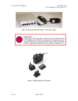
The Canopy T1/E1 Multiplexer is available in two power configurations:
◦
an external 3.3-v DC power source from a 120/240-v AC adapter (supplied
by Canopy)
WARNING!
An external AC surge suppression device must be used with the Canopy
T1/E1 Multiplexer. For infrastructure installations, Canopy Engineering
recommends an AC line surge suppression unit that meets the standard
IEC 801-5 (EN61000-4-5) Maximum Surge Voltage (1.2x50µsec) 6 KV.
◦
a connection to an external
−
48 v DC supply.
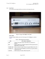
The Canopy T1/E1 Multiplexer is illustrated with Canopy Backhaul Modules (BHs) in
Figure 1
.
Issue
3


