Canopy
T1/E1
Multiplexer
September
2004
T1/E1
Multiplexer
FPGA
Version
3.4
Page
15 of 73
LED
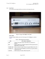
LED indicator descriptions
LAN ACT
OFF when no activity; BLINKING when frames are being transmitted or
received on the line
T1/E1 Sync
ON when the port is synchronized (no alarm); OFF when Loss of signal
(LOS); one LED for each T1/E1
1.2.6
Features
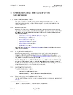
The Canopy T1/E1 Multiplexer
◦
installs
easily.
◦
multiplexes up to 4 T1 or 3 E1 circuits onto a Canopy Backhaul point-to-point
link.
◦
enables T1/E1 extension over Ethernet networks.
◦
supports
−
synchronous TDM-based services over wireless Ethernet networks.
−
CAS signaling transparent to all other signaling protocols on T1/E1.
−
10Base-T/100Base-TX uplink to the network.
−
management
interfaces.
−
simplified troubleshooting through T1/E1 line loopback test.
1.2.7
Specifications
Physical Specifications
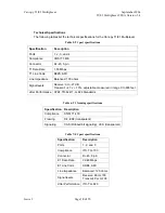
Table 4
lists the physical specifications for the Canopy T1/E1 Multiplexer.
Table 4: Canopy T1/E1 Multiplexer physical specifications
Specification Description
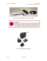
Option 1: 100/240 v, 47
−
63 Hz, 0.4 A (+3.3 v DC)
DC Power
Option 2:
−
48 v DC
LAN Connection
2-100Base-TX, RJ-45 cable provided
T1/E1 Connections
4
Control Port
RS-232, DB9 (female)
Indicators
power, ready, Canopy BH Ethernet link; Canopy BH Ethernet
activity; LAN Ethernet link; LAN Ethernet activity; T1/E1
synchronization (one per port)
Temperature
0° C to 40° C
Humidity 95%
non-condensing
Dimensions
1.52” (3.86 cm) high x 5.57" (14.15 cm) wide and 7.50" (19.05 cm)
deep
Weight
1.5 pounds (680 grams)
Issue
3


