Canopy
T1/E1
Multiplexer
June
2004
T1/E1
Multiplexer
Release
3.1
11 of 69
1.2.1
Ethernet
Interface
The Ethernet physical layer auto-negotiation should be set to
on
for both sides of the
Canopy T1/E1 Multiplexer.
RJ-45 connector pin-outs for the Ethernet cable from the BH to the Canopy port of the
Canopy T1/E1 Multiplexer are illustrated in
Figure 13
on Page
28
.
1.2.2
Standards
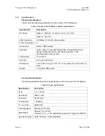
The Canopy T1/E1 Multiplexer conforms to the following standards:
◦
G.703
◦
TR-AT&TG2411
◦
G.823
◦
IEEE
802.3
◦
G.824
◦
EMC Class A compliance – EN 55022 Class A
◦
ANSI
T1.403
1.2.3
IDU
Physical
Description
The unit provides a compact, simple to configure, and easily scalable solution for
transporting T1/E1 services over Canopy’s wireless Ethernet-based networks.
1.2.4
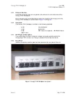
Rear
Panel
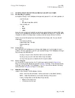
Interface connections and the power port are located on the rear panel of the unit.
Figure 3: Canopy T1/E1 Multiplexer rear panel
Issue
1
Page

