Canopy
T1/E1
Multiplexer
June
2004
T1/E1
Multiplexer
Release
3.1
29 of 69
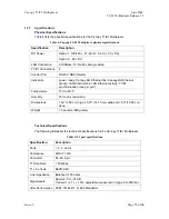
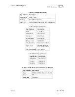
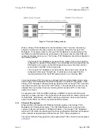
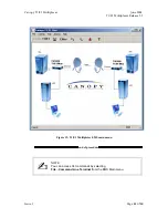
Perform this procedure to connect the cables to the T1/E1 unit.
Perform this procedure to connect the cables to the T1/E1 unit.
Procedure 2: Connecting cables to T1/E1 unit
Procedure 2: Connecting cables to T1/E1 unit
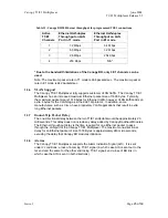
1. Connect the T1/E1 cables to the T1/E1 ports.
NOTE:
There is a one-to-one relationship between the T1/E1 ports on the
Canopy T1/E1 Multiplexer. This means, that the T1/E1 cable connected to the
T1/E1 Port 1 on one of the Canopy T1/E1 Multiplexers, must also be connected
to Port 1 on the other.
1. Connect the T1/E1 cables to the T1/E1 ports.
NOTE:
There is a one-to-one relationship between the T1/E1 ports on the
Canopy T1/E1 Multiplexer. This means, that the T1/E1 cable connected to the
T1/E1 Port 1 on one of the Canopy T1/E1 Multiplexers, must also be connected
to Port 1 on the other.
2. Connect the Ethernet cables to the Ethernet ports.
2. Connect the Ethernet cables to the Ethernet ports.
3. Connect the power cable to the power connector.
3. Connect the power cable to the power connector.
end of procedure
2.2.5
Connecting
Power
to
the
Canopy
T1/E1
Multiplexer
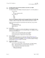
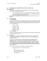
The Canopy T1/E1 Multiplexer is available in two power configurations:
◦
an external 3.3-v DC power source (supplied by Canopy)
◦
an
external
−
48 v DC power supply with a terminal strip that plugs into the back
of the Canopy T1/E1 Multiplexer.
WARNING!
Disconnect power before proceeding.
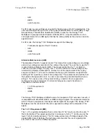
Follow this procedure to connect the supplied AC Adapter. (+3.3 v DC power source).
Procedure 3: Connecting the AC adapter (+3.3 v DC power source)
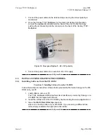
1. Ensure the AC Adapter is disconnected from the building mains and connect to
the DC in port on the rear of the Canopy T1/E1 Multiplexer.
end of procedure
Follow this procedure to connect the to an external
−
48 v DC power source.
Procedure 4: Connecting the
−
48 v DC power source
CAUTION!
Ensure correct polarity before connecting external DC supply to Canopy
T1/E1 Multiplexer.
Issue
1
Page

