background image

13A

13B

EN

EN

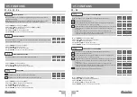
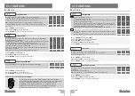
ERL ERRORS

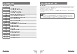
06. COMPONENTS TEST

If the display shows the error 

ERL1, 2, 3 

it means that one of the input phases is missing or

that the motor connections are incorrect.

Check all connections and try again.

To remove errors from the display you just need to click on any button on the control panel

or in charge.

NOTES:

• This control board was developed only to work with Motorline motors, however if you 

want to work with motors from other manufacturers make sure that this motor is in star 

configuration and that it is a 400V motor that does not exceed 1500W.

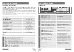
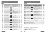
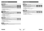
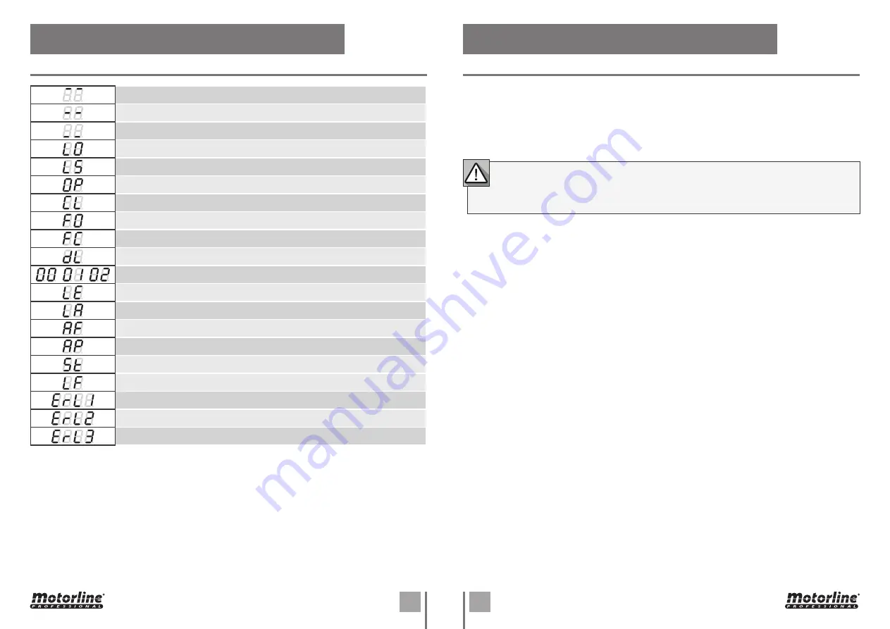
INDICAÇÕES DO DISPLAY

05. FUNCTIONS

IN STOP POSITION, FULLY OPEN

IN STOP POSITION, MIDDLE POSITION

IN STOP POSITION, FULLY CLOSED

TOTAL OPENING BUTTON PRESSED

PEDESTRIAN OPENING BUTTON PRESSED

CONTROL BOARD RUNNING OPENING COURSE

CONTROL BOARD RUNNING CLOSING COURSE

END OF OPENING COURSE TIME

END OF CLOSING COURSE TIME

ALL TRASMITTERS DELETED

TRANSMITTER ADDED IN THE INDICATED POSITION

OBSTRUCTED PHOTOCELL

OBSTRUCTED PHOTOCELL 2

IN PAUSE TIME

IN PEDESTRIAN PAUSE TIME

EMERGENCY BUTTON PRESSED

NO LIMIT-SWITCHES INSTALL

PHASE 1 OR MOTOR FAILURE

PHASE 2 OR MOTOR FAILURE

PHASE 3 OR MOTOR FAILURE

Содержание MC410

Страница 1: ...F 1 F 2 F 3 L1 L2 V L3 T1 LAMP T2 T3 LS LO OL CL LE LA ST PU LS LO ST PU OL LS LE LA R G B Y V v1 2 REV 03 2021 MC410 MC410 EN INSTALLER AND USER S MANUAL...

Страница 2: ...cable in countries with recycling systems This marking on the product or literature indicates that the product and electronic accessories eg Charger USB cable electronic material controls etc should n...

Страница 3: ...with experienced in terms of usage of the product in a safe manner and who understands the risks and dangers involved Children shouldn t play with the product or opening devices to avoid the motorize...

Страница 4: ...esanyrepairormodification unlocktheautomatism turn off the power and do not use it until all safety conditions have been met In the event of tripping of circuits breakers of fuse failure locate the ma...

Страница 5: ...light or Flashing light This output allows the connection of a courtesy light or a Flashing light CN2 11 V Power supply 24Vdc 325mA max 12 GND Power supply 24Vdc 325mA max 24Vdc Auxiliary Power Supply...

Страница 6: ...U R G B Y V TX RX TX RX R G B Y V F 2 F 3 L1 L2 L3 T1 LAMP T2 T3 V LS LO OL CL ST PU EN 03 INSTALLATION INSTALLATION MAP STARK Pedestrian or Close Pushbutton Motor connection Total or Open Pushbutton...

Страница 7: ...2 COM 3 4 NC NO TX RX 9 10 10 9 1 2 3 11 4 6 5 11 8 7 1 2 3 5 6 4 7 8 EN 03 INSTALLATION INSTALLATION MAP KVM105 KVM110 KVM115 Connections Motor Pushbutton Flashlight Example Control Board Loading do...

Страница 8: ...ion appears 05 Press the command button you want to program The display will blink and move to the next free location 03 Press cmd once to confirm 01 Press the cmd button for 3 sec PROGRAMMING TRANSMI...

Страница 9: ...ST emergency button 00 01 Operating logic Automatic mode function 00 01 Step by step mode function Condominium mode function Flashing light Flashing opening and closing 00 00 Step by step mode functio...

Страница 10: ...1 second 04 When programming is complete the display returns to the initial state This menu allows you to program the engine s working time in a semi automatic way allowing you to manually define the...

Страница 11: ...disable photocells Define whether this security will act when opening or closing the gate 00 acts on closing 01 acts on opening Define the behavior that the gate will have when this security is activ...

Страница 12: ...hing light will flash the 1st free position appears in the display Each time you store 1 command the control board will exit remote programming If you want to memorize more commands you will always ha...

Страница 13: ...eters 03 Press MENU to edit the value 04 Use UP and DW to change the value 05 Press MENU for 2sec to save the new value DECELERATION SPEED This menu allows you to adjust the deceleration speed DEFAULT...

Страница 14: ...otor is in star configuration and that it is a 400V motor that does not exceed 1500W INDICA ES DO DISPLAY 05 FUNCTIONS IN STOP POSITION FULLY OPEN IN STOP POSITION MIDDLE POSITION IN STOP POSITION FUL...

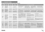
Страница 15: ...in order to find out if it has problems see page 11B 3 f the motors work the problem is from control board Pull it out and send it to our MOTORLINE technical services for diagnosis 4 If the motors don...

Отзывы: