background image

EN

17

make sure that any protection or safety devices, in ad

-

dition to the manual release, work correctly;
place  the  automation  identification  plate  at  a  clearly 

visible point;
keep the manuals and technical files of all the devices 

used to create the automation;
at the end of the automation installation it is advisable 

to hand over the manuals relating to the warnings in

-

tended for the end user;

ATTENTION !

Frequently examine the installation for imbalance 

where applicable and signs of wear or damage to 

cables, springs and mounting. Do not use if repair 

or adjustment is necessary.

ATTENTION !

The automation system component packaging 

material must be disposed of in full observance of 

current local waste disposal legislation.
Motorisation Plus reserves the right to amend the-

se instructions if necessary; they and/or any more 

recent versions are available at www.motorisa-

tionplus.com.

the  system  power  supply  line  must  include  a  circuit 

breaker device with a contact gap allowing complete 

disconnection in the conditions specified by class III 

overvoltage; 
use unions with IP55 or higher protection when con

-

necting hoses, pipes or cable glands;
the electrical system upstream of the automation sy

-

stem must comply with the relevant regulations and be 

constructed to good workmanship standards;
this appliance can be used by children aged from 8 

years and above and persons with reduced physical, 

sensory  or  mental  capabilities  or  lack  of  experience 

and knowledge if they have been given supervision or 

instruction concerning use of the appliance in a safe 

way and understand the hazards involved;
before  starting  the  automation  system,  ensure  that 

there is no-one in the immediate vicinity;
before proceeding with any cleaning or maintenance 

work on the automation system, disconnect it from the 

electrical mains; 
special care must be taken to avoid crushing between 

the part operated by the automation system and any 

fixed parts around it; 
children must be supervised to ensure that they do not 

play with the equipment; 
that the drive cannot be used with a driven part incor

-

porating  a  wicket  door  unless  the  drive  can  only  be 

operated with the wicket door in the safe position;
install any fixed control at a height of at least 1,5m and 

within sight of the door but away from moving parts;
after installation, ensure that parts of the door do not 

extend over public footpaths or roads; 
when the appliance is provided with a separate stop 

button, that stop button shall be unambiguously iden

-

tifiable;
install the automation exclusively on gates operating 

on flat surfaces, that is, they are not installed on an up 

or down tilt;
install exclusively on gates that are sturdy enough and 

suitable to withstand the loads generated by the auto

-

mation itself;
do not subject the automation to direct jets of water, 

such as sprinklers or pressure washers;
if  the  automation  system  exceeds  20  kg  in  weight, 

it  must  be  handled  using  safety  lifting  devices  (IEC 

60335-2-103: 2015);
provide appropriate safety protections in order to avoid 

crushing and becoming trapped between the moving 

guided part and any surrounding fixed elements;

Содержание FLASH24

Страница 1: ...enterr Undergrounded gear motor Motorredutor interrado Instructions et avertissements pour l installation et l usage Instructions and warnings for installation and use Instru es e advert ncias para a...

Страница 2: ...sions PT Dimens es globais Kg FR Poids maximum du battant du portail EN Maximum weight of the gate door m FR Longueur maximum du battant du portail EN Maximum length of the gate door Fig 2 FR Limites...

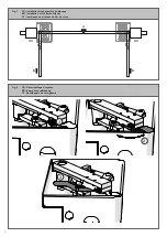
Страница 3: ...da caixa de funda o Fig 5 FR Mise en place du motor ducteur EN Installing the motor reducer PT Instala o do motorredutor Fig 6 FR Installation des baguettes de blocage EN Installation of the limit swi...

Страница 4: ...g 7 FR Installation des baguettes de blocage EN Installation of the limit switches PT Instala o dos trav es de fim de curso Fig 8 FR D verrouillage d urgence EN Emergency unblocking PT Desbloqueio de...

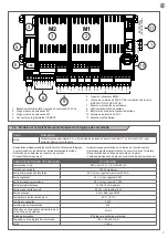
Страница 5: ...age 8 page 8 page 9 page 10 3 Contr les pr liminaires page 10 4 4 1 4 2 4 3 4 4 4 5 4 6 Installation du produit Installation Connexions lectriques D verrouillage d urgence Branchements lectriques Conn...

Страница 6: ...chapitre Caract ristiques techniques Ne pas effectuer l installation si ne serait ce qu un seul de ces dispositifs n est pas adapt ce type d utilisation v rifier que les dispositifs achet s sont suff...

Страница 7: ...sus un criteau indiquant MAINTE NANCE EN COURS tous les dispositifs doivent tre raccord s une ligne d a limentation lectrique avec mise la terre de s curit le produit ne peut pas tre consid r comme un...

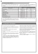
Страница 8: ...e protection IP IP67 Dimensions L P H mm 412 346 160 Poids Kg 10 8 Temp rature de fonctionnement C 20 55 Poid maximal vantail Kg 600 2 2 Mod le et caract ristiques techniques Code Description FLASH24...

Страница 9: ...clignotant 24 Vcc non r gul e 25 W Sortie clairage automatique 24 Vcc non r gul e 15 W Sortie serrure lectrique 12 Vca 15 VA maximum Sortie voyant portail ouvert 24 Vcc non r gul e 5 W Entr e antenne...

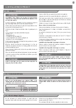
Страница 10: ...seau d alimentation pr voir un dispositif de d connexion avec une distance d ouverture des contacts permettant la d connexion compl te dans les conditions indiqu es par la cat gorie de surtension III...

Страница 11: ...pivot de la caisse B la bride de commande A Fixer avec une soudure forte le vantail du portail sur le levier de d verrouillage C ensuite positionner tout sur l trier de commande A en correspondance du...

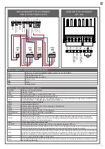
Страница 12: ...2 PROCHE PARTIEL PAS PAS COMMUN COMMUN BORD DE S CURIT VERROUILLAGE LECTRIQUE N GATIF SBS M1 M2 BATTERIES ACCESSOIRES COMMUN CLAT COMMON FLASH SHIELD ANT PH1 RX 2 1 PH1 TX 4 4 Branchements lectriques...

Страница 13: ...llules 24 Vcc non r gul e maximum 250 mA PH1 Photocellules fermeture contact NF entre PH1 et COM La photocellule intervient tout moment durant la ferme ture de l automatisme pour bloquer imm diatement...

Страница 14: ...d urgence autres en effectuant des essais d ouverture de fermeture et d arr t du portail ou de la porte l aide des dispositifs de commande reli s transmetteurs touches s lecteurs Proc der la mesure d...

Страница 15: ...18 p 18 p 18 p 19 p 20 3 Preliminary checks p 20 4 4 1 4 2 4 3 4 4 4 5 4 6 Product installation Installation Electrical connections Emergency unblocking Electrical connections Connection of sensor for...

Страница 16: ...ices is not suitable for its intended purpose check that the devices purchased are sufficient to gua rantee system safety and functionality perform a risk assessment including a list of the es sential...

Страница 17: ...owledge if they have been given supervision or instruction concerning use of the appliance in a safe way and understand the hazards involved before starting the automation system ensure that there is...

Страница 18: ...120 Capacitor F Thermoprotection C Degree of protection IP IP67 Dimensions L P H mm 412 346 160 Weight Kg 10 8 Operating temperat C 20 55 Leaves maximum weight Kg 600 2 2 Model and technical characte...

Страница 19: ...250mA Flashing light output 24Vdc without regulation 25W Courtesy light output 24Vdc without regulation 15W Electric lock output 12Vac maximum 15VA Gate open warning light output 24Vdc without regula...

Страница 20: ...r system with a disconnecting device with a gap of contacts enabling full disconnection under the conditions dictated by the overvoltage category III Ensure that all materials used for the installatio...

Страница 21: ...ershallcheckthatthetemperature range marked on the drive is suitable for the location Ensure that the concrete used is prop erly cured prior to proceeding with the following steps To operate the engin...

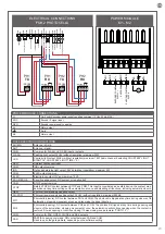
Страница 22: ...2 CLOSE PARCIAL STEP BY STEP COMMON COMMON SAFETY EDGE ELECTRIC LOCK NEGATIVE SBS M1 M2 BATTERIES ACCESSORY COMMON FLASH SHIELD ANT PH1 RX 2 1 PH1 TX SHIELD ANT COMMON FLASH 4 4 Electrical connections...

Страница 23: ...PH1 and COM The photocell is tripped at any time during closure of the automation stopping movement at once and reversing the travel direction PH2 Photocells opening NC contact between PH2 and COM The...

Страница 24: ...by performing gate or door opening closing and stop tests using the connected control devices transmitters buttons or switches perform the impact measurements as required by the EN12453 standard adju...

Страница 25: ...8 p 28 p 28 p 28 p 29 p 30 3 Verifica es preliminares p 30 4 4 1 4 2 4 3 4 4 4 5 4 6 Instala o do produto Instala o Liga es el tricas Desbloqueio de emerg ncia Liga es el tricas Conex o do sensor para...

Страница 26: ...intrus o Se desejar prote ger se de forma eficaz necess rio agregar na auto ma o outros dispositivos o produto s pode ser utilizado depois que foi feita a ATEN O INSTRU ES ORIGINAIS instru es importan...

Страница 27: ...rtar a corrente completamente nas condi es estabelecidas pela ca tegoria de sobretens o III Para a liga o de tubos r gidos e flex veis ou passa fios utilizar liga es conformes ao grau de prote o IP55...

Страница 28: ...mperatura de utiliza o C 20 55 Peso m ximo da folha Kg 600 2 2 Modelos e caracter sticas t cnicas C DIGO DESCRI O FLASH24 Para port es de batente com comprimento m ximo de 3 5 m 24 Vdc do motor sem en...

Страница 29: ...o 250mA Sa da da luz de sinaliza o intermitente 24Vdc n o regulado 25W Sa da da luz de cortesia 24Vdc n o regulado 15W Sa da da fechadura el trica 12Vac 15VA m ximo Sa da do led de port o aberto 24Vdc...

Страница 30: ...ede de alimenta o do sistema um dispositivo de desconex o com uma dist ncia de abertura dos contactos que permita a desconex o completa nas condi es exigidas pela categoria de sobretens o III Verifica...

Страница 31: ...e temperatura referida no dispositivo de automa o adequada para a posi o em que deve ser instalado Antes de dar seguimento s etapas seguintes respeitar a fase de endurecimento do bet o Para operar o m...

Страница 32: ...C LULA 1 FOTOC LULA 2 PERTO PARCIAL PASSO A PASSO COMUM COMUM LIMITE DE SEGURAN A BLOQUEIO EL TRICO NEGATIVO SBS M1 M2 BATERIAS ACESS RIO COMUM FLASH COMUM FLASH PH1 RX 2 1 PH1 TX 4 4 Liga es el trica...

Страница 33: ...toc lula atua em qualquer momento durante o fecho da automa o provocando o bloqueio imediato do movimento e invertendo o sentido de movimenta o PH2 Fotoc lulas abertura contacto NC entre PH2 e COM A f...

Страница 34: ...aragem do port o ou da porta atrav s dos dispositivos de comando ligados emissores bot es seletores Fazer as medi es da for a de impacto conforme previsto pela norma EN12453 regulando as fun es de vel...

Страница 35: ...eur enterr Undergrounded gear motor Motorredutor interrado Instructions et avertissements destin s l utilisation final Instructions and warnings for the end user Instru es e advert ncias destinadas ao...

Страница 36: ...t lieu que lorsque le battant est arr t Fig 2 Entretien Comme toute machine l automation a besoin d un entretien p riodique permettant une majeure dur e de fonction nement en toute s curit D finir un...

Страница 37: ...Fig 2 Release and manual movement before performing this operation pay attention that the device can be released only when the door is stationary Fig 2 Maintenance Like any machine your automation nee...

Страница 38: ...a isto necess rio efectuar o desbloqueio manual Fig 2 Desbloqueio e movimento manual antes de executar esta opera o preste aten o que o desbloqueio pode ser feito apenas quando o port o estiver parado...

Страница 39: ...39 IMAGES Fig 1 FR Attention EN Attention PT Aten o...

Страница 40: ...40 Fig 2 FR D verrouillage d urgence EN Emergency unblocking PT Desbloqueio de emerg ncia 1 2 3...

Страница 41: ...INSTALLER DATA INSTALLER DATA DATE SIGNATURE...

Страница 42: ...42 NOTE...

Страница 43: ...43...

Страница 44: ...580UNDMO REV 02 Instruction version LABEL HABITAT SAS rue L o Lagrange 10 27950 Saint Marcel France T l phone 33 02 32 21 21 63 www motorisationplus com...

Отзывы: