background image

EN

37

6 - INSTRUCTIONS AND WARNINGS FOR THE END USER

Motorisation Plus produces systems for the automation of gates, 

garage  doors,  automatic  doors,  shutters,  parking  lots  and  road 

barriers.  However,  Motorisation  Plus  is  not  the  manufacturer  of 

your  automation  system, which  is rather  the result  of a process 

of  analysis,  evaluation,  selection  of  materials,  and  installation 

performed by your own installer. Each automated system is unique 

and  only  your  installer  has  the  experience  and  professionalism 

required to create a system to suit your needs, safe and reliable over 

time, and carried out in a workmanlike manner, i.e. compliant with 

the current regulations. Even if your automation system meets the 

security level required by law, this does not exclude the existence 

of “residual risks”, i.e. the possibility that it may cause dangerous 

situations, usually as a result of improper or irresponsible use; for 

this reason we would like to give you some suggestions:
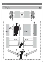
• Before using the automation for the first time, ask the installer to 

explain the origin of residual risks (Fig.1).
• Keep this manual for future use and deliver it to any new owner 

of the automation.
•  Inappropriate  or  improper  use  of  the  automation  can  make  it 

dangerous: do not command the movement of the automation if 

people, animals or things are in its range.
• Children: If properly designed, an automation system ensures a 

high degree of security, preventing movement in the presence of 

people or things with its detection systems, and ensuring always 

predictable  and  safe  activation.  It  is  prudent  to  prevent  children 

from playing near the automation and keep remote controls out of 

their reach to prevent accidental activation.

• Malfunctions: As soon as you notice any malfunctions, disconnect 

the system from the power supply and operate the manual release. 

Do not attempt any repairs by yourself, but require the assistance 

of your installer: meanwhile, the system can operate like a non-

automated opening device after releasing the motor reducer with 

the release key supplied with the system.
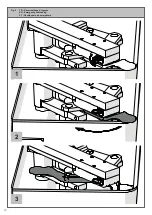
• In case of failures or power failures: While awaiting the arrival of 

your installer or the restore of the electricity, if the system is not 

equipped with backup batteries, the automation can be operated 

as  any  normal  non-automated  opening  device.  To  do  this,  you 

must run the manual release (Fig.2).

Release and manual movement: before performing this operation 

pay attention that the device can be released only when the door 

is stationary (Fig.2).
• Maintenance: Like any machine, your automation needs periodic 

maintenance to ensure its long life and total safety. Agree with your 

installer on a maintenance plan on a periodic basis; Motorisation 

Plus recommends a frequency of 6 months for normal domestic 

use, but this period may vary depending on the intensity of use. All 

inspection, maintenance or repairs should be performed only by 

qualified personnel.

Cleaning and user maintenance shall not be made by children 

without supervision.

• Do not change the system and control or programming parameters 

of the automation: the responsibility lies with your installer.
•  The  testing,  routine  maintenance  and  any  repairs  must  be 

documented  by  the  person  who  performs  them,  and  related 

documents must kept by the owner.
The only interventions that are possible for the user and should 

be  carried  out  periodically  are  the  cleaning  of  the  slides  and 

photocells, as well as the removal of any leaves or rocks that could 

hinder the automation. To prevent anyone from activating the gate 

or door, before proceeding, remember to release the automation 

and clean only with a cloth slightly dampened with water.
•  Disposal: At  the  end  of  the  automation  useful  life,  make  sure 

ATTENTION!

ATTENTION!

A more recent version of the manual supplied may be 

available for download at www.motorisationplus.com; check 

for updates.

that the dismantling is carried out by qualified personnel and the 

materials are recycled or disposed of according to local regulations 

in force.
• Operate the gate or door (with remote control, key switch, etc..); 

if  everything  is  working  properly,  the  gate  or  the  door  will  open 

and  close  normally,  otherwise  the  flashing  light  flashes  and  the 

maneuver does not start.

With the safeties out of use, the automation must be repaired as 

soon as possible.

Replacing the remote control battery: if your remote control seems 

to  work  worse  or  not  work  at  all  after  a  while,  this  may  simply 

depend on the exhaustion of the battery (depending on use, it may 

take several months to over a year). In that case, you will see that 

the confirmation of transmission light does not turn on, or comes 

on only briefly. 
The batteries contain polluting substances: do not throw them in 

the garbage but use the methods prescribed by local regulations.
Thank  you  for  choosing  Motorisation  Plus;  for  more  information 

feel free to visit our website www.motorisationplus.com.

Содержание FLASH24

Страница 1: ...enterr Undergrounded gear motor Motorredutor interrado Instructions et avertissements pour l installation et l usage Instructions and warnings for installation and use Instru es e advert ncias para a...

Страница 2: ...sions PT Dimens es globais Kg FR Poids maximum du battant du portail EN Maximum weight of the gate door m FR Longueur maximum du battant du portail EN Maximum length of the gate door Fig 2 FR Limites...

Страница 3: ...da caixa de funda o Fig 5 FR Mise en place du motor ducteur EN Installing the motor reducer PT Instala o do motorredutor Fig 6 FR Installation des baguettes de blocage EN Installation of the limit swi...

Страница 4: ...g 7 FR Installation des baguettes de blocage EN Installation of the limit switches PT Instala o dos trav es de fim de curso Fig 8 FR D verrouillage d urgence EN Emergency unblocking PT Desbloqueio de...

Страница 5: ...age 8 page 8 page 9 page 10 3 Contr les pr liminaires page 10 4 4 1 4 2 4 3 4 4 4 5 4 6 Installation du produit Installation Connexions lectriques D verrouillage d urgence Branchements lectriques Conn...

Страница 6: ...chapitre Caract ristiques techniques Ne pas effectuer l installation si ne serait ce qu un seul de ces dispositifs n est pas adapt ce type d utilisation v rifier que les dispositifs achet s sont suff...

Страница 7: ...sus un criteau indiquant MAINTE NANCE EN COURS tous les dispositifs doivent tre raccord s une ligne d a limentation lectrique avec mise la terre de s curit le produit ne peut pas tre consid r comme un...

Страница 8: ...e protection IP IP67 Dimensions L P H mm 412 346 160 Poids Kg 10 8 Temp rature de fonctionnement C 20 55 Poid maximal vantail Kg 600 2 2 Mod le et caract ristiques techniques Code Description FLASH24...

Страница 9: ...clignotant 24 Vcc non r gul e 25 W Sortie clairage automatique 24 Vcc non r gul e 15 W Sortie serrure lectrique 12 Vca 15 VA maximum Sortie voyant portail ouvert 24 Vcc non r gul e 5 W Entr e antenne...

Страница 10: ...seau d alimentation pr voir un dispositif de d connexion avec une distance d ouverture des contacts permettant la d connexion compl te dans les conditions indiqu es par la cat gorie de surtension III...

Страница 11: ...pivot de la caisse B la bride de commande A Fixer avec une soudure forte le vantail du portail sur le levier de d verrouillage C ensuite positionner tout sur l trier de commande A en correspondance du...

Страница 12: ...2 PROCHE PARTIEL PAS PAS COMMUN COMMUN BORD DE S CURIT VERROUILLAGE LECTRIQUE N GATIF SBS M1 M2 BATTERIES ACCESSOIRES COMMUN CLAT COMMON FLASH SHIELD ANT PH1 RX 2 1 PH1 TX 4 4 Branchements lectriques...

Страница 13: ...llules 24 Vcc non r gul e maximum 250 mA PH1 Photocellules fermeture contact NF entre PH1 et COM La photocellule intervient tout moment durant la ferme ture de l automatisme pour bloquer imm diatement...

Страница 14: ...d urgence autres en effectuant des essais d ouverture de fermeture et d arr t du portail ou de la porte l aide des dispositifs de commande reli s transmetteurs touches s lecteurs Proc der la mesure d...

Страница 15: ...18 p 18 p 18 p 19 p 20 3 Preliminary checks p 20 4 4 1 4 2 4 3 4 4 4 5 4 6 Product installation Installation Electrical connections Emergency unblocking Electrical connections Connection of sensor for...

Страница 16: ...ices is not suitable for its intended purpose check that the devices purchased are sufficient to gua rantee system safety and functionality perform a risk assessment including a list of the es sential...

Страница 17: ...owledge if they have been given supervision or instruction concerning use of the appliance in a safe way and understand the hazards involved before starting the automation system ensure that there is...

Страница 18: ...120 Capacitor F Thermoprotection C Degree of protection IP IP67 Dimensions L P H mm 412 346 160 Weight Kg 10 8 Operating temperat C 20 55 Leaves maximum weight Kg 600 2 2 Model and technical characte...

Страница 19: ...250mA Flashing light output 24Vdc without regulation 25W Courtesy light output 24Vdc without regulation 15W Electric lock output 12Vac maximum 15VA Gate open warning light output 24Vdc without regula...

Страница 20: ...r system with a disconnecting device with a gap of contacts enabling full disconnection under the conditions dictated by the overvoltage category III Ensure that all materials used for the installatio...

Страница 21: ...ershallcheckthatthetemperature range marked on the drive is suitable for the location Ensure that the concrete used is prop erly cured prior to proceeding with the following steps To operate the engin...

Страница 22: ...2 CLOSE PARCIAL STEP BY STEP COMMON COMMON SAFETY EDGE ELECTRIC LOCK NEGATIVE SBS M1 M2 BATTERIES ACCESSORY COMMON FLASH SHIELD ANT PH1 RX 2 1 PH1 TX SHIELD ANT COMMON FLASH 4 4 Electrical connections...

Страница 23: ...PH1 and COM The photocell is tripped at any time during closure of the automation stopping movement at once and reversing the travel direction PH2 Photocells opening NC contact between PH2 and COM The...

Страница 24: ...by performing gate or door opening closing and stop tests using the connected control devices transmitters buttons or switches perform the impact measurements as required by the EN12453 standard adju...

Страница 25: ...8 p 28 p 28 p 28 p 29 p 30 3 Verifica es preliminares p 30 4 4 1 4 2 4 3 4 4 4 5 4 6 Instala o do produto Instala o Liga es el tricas Desbloqueio de emerg ncia Liga es el tricas Conex o do sensor para...

Страница 26: ...intrus o Se desejar prote ger se de forma eficaz necess rio agregar na auto ma o outros dispositivos o produto s pode ser utilizado depois que foi feita a ATEN O INSTRU ES ORIGINAIS instru es importan...

Страница 27: ...rtar a corrente completamente nas condi es estabelecidas pela ca tegoria de sobretens o III Para a liga o de tubos r gidos e flex veis ou passa fios utilizar liga es conformes ao grau de prote o IP55...

Страница 28: ...mperatura de utiliza o C 20 55 Peso m ximo da folha Kg 600 2 2 Modelos e caracter sticas t cnicas C DIGO DESCRI O FLASH24 Para port es de batente com comprimento m ximo de 3 5 m 24 Vdc do motor sem en...

Страница 29: ...o 250mA Sa da da luz de sinaliza o intermitente 24Vdc n o regulado 25W Sa da da luz de cortesia 24Vdc n o regulado 15W Sa da da fechadura el trica 12Vac 15VA m ximo Sa da do led de port o aberto 24Vdc...

Страница 30: ...ede de alimenta o do sistema um dispositivo de desconex o com uma dist ncia de abertura dos contactos que permita a desconex o completa nas condi es exigidas pela categoria de sobretens o III Verifica...

Страница 31: ...e temperatura referida no dispositivo de automa o adequada para a posi o em que deve ser instalado Antes de dar seguimento s etapas seguintes respeitar a fase de endurecimento do bet o Para operar o m...

Страница 32: ...C LULA 1 FOTOC LULA 2 PERTO PARCIAL PASSO A PASSO COMUM COMUM LIMITE DE SEGURAN A BLOQUEIO EL TRICO NEGATIVO SBS M1 M2 BATERIAS ACESS RIO COMUM FLASH COMUM FLASH PH1 RX 2 1 PH1 TX 4 4 Liga es el trica...

Страница 33: ...toc lula atua em qualquer momento durante o fecho da automa o provocando o bloqueio imediato do movimento e invertendo o sentido de movimenta o PH2 Fotoc lulas abertura contacto NC entre PH2 e COM A f...

Страница 34: ...aragem do port o ou da porta atrav s dos dispositivos de comando ligados emissores bot es seletores Fazer as medi es da for a de impacto conforme previsto pela norma EN12453 regulando as fun es de vel...

Страница 35: ...eur enterr Undergrounded gear motor Motorredutor interrado Instructions et avertissements destin s l utilisation final Instructions and warnings for the end user Instru es e advert ncias destinadas ao...

Страница 36: ...t lieu que lorsque le battant est arr t Fig 2 Entretien Comme toute machine l automation a besoin d un entretien p riodique permettant une majeure dur e de fonction nement en toute s curit D finir un...

Страница 37: ...Fig 2 Release and manual movement before performing this operation pay attention that the device can be released only when the door is stationary Fig 2 Maintenance Like any machine your automation nee...

Страница 38: ...a isto necess rio efectuar o desbloqueio manual Fig 2 Desbloqueio e movimento manual antes de executar esta opera o preste aten o que o desbloqueio pode ser feito apenas quando o port o estiver parado...

Страница 39: ...39 IMAGES Fig 1 FR Attention EN Attention PT Aten o...

Страница 40: ...40 Fig 2 FR D verrouillage d urgence EN Emergency unblocking PT Desbloqueio de emerg ncia 1 2 3...

Страница 41: ...INSTALLER DATA INSTALLER DATA DATE SIGNATURE...

Страница 42: ...42 NOTE...

Страница 43: ...43...

Страница 44: ...580UNDMO REV 02 Instruction version LABEL HABITAT SAS rue L o Lagrange 10 27950 Saint Marcel France T l phone 33 02 32 21 21 63 www motorisationplus com...

Отзывы: