MOTECK MK35 Скачать руководство пользователя страница 8

3.4.5


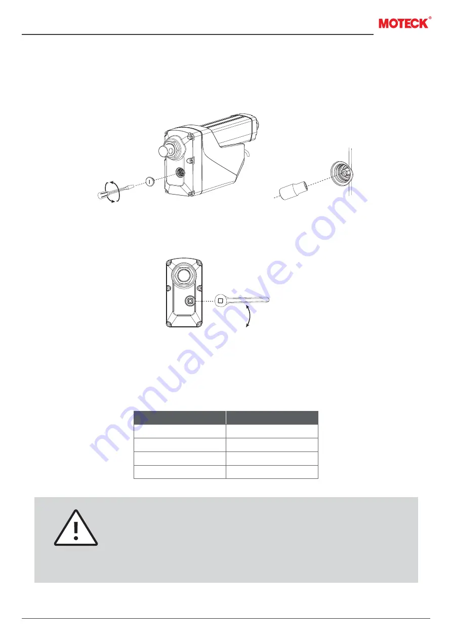
Installation and operation of hand crank

(1)  When installing the actuator, please make sure that there is enough space between the rear connector and any  
       objects behind it so that the hand crank can be operated.
(2)  Please use a flat-head screwdriver to remove the cover and connect with a 6mm hexagon socket.

(3)  Use a wrench to operate as a hand crank.

(4)  Under the maximum load of the actuator, the maximum torque required to drive the extension tube with the  
       hand crank is about 1.4Nm.
(5)  The distance traveled by the actuator per rotation of the hand crank is related to the gear ratio options of the  
       actuator. Please refer to the table below.

www.moteck.com

8

3.4.3


Force and orientation

(1)  The actuator can be installed in any orientation and can withstand push and pull loads.
(2)  When installing the actuator, make ensure that the force of the load acts on the central axis of the extension tube  
       and rear connector.
(3)  Use only solid and sized mounting pins. The mounting pins must be strong enough to support the load and  
       prevent it from falling off after installation.
(4)  The mounting pins must be parallel to each other on the same plane, as shown in the sketch below.
(5)  If the actuator is used on the equipment to rotate with the mounting pin as the axis, it must be ensured the  
       housing and other mechanical parts will not interfere and damage the actuator and equipment in the full range  
       of movement.

3.4.4


Cables and anti-pull lid

Before the actuator is shipped, the power cord and signal cable have been plugged in and the anti-pull lid has been 
installed. Only the CAN Bus version (control option J00) needs to remove this lid and unplug the power cord when 
manually changing the address through hardware (see 4.2.2.2). But please note that when installing the actuator, 
you must ensure that there is enough space to remove the anti-pull lid with tools.

Gear type

10
15
20
30

mm /rev

1.349
0.804
0.609
0.379

  Before using the hand crank, be sure to turn off the actuator power. Do not  

    apply torque exceeding 1.7Nm on the hand crank.

  Do not move the extension tube to both ends of the stroke, otherwise the                                           

    actuator might be damaged.

  Do not use any type of automatic drill or power tools to drive the manual  

    crank.

Содержание MK35

Страница 1: ...Technical changes may be made to improve the product without notice 2022 5_V1 0 www moteck com Revision Actuator MK35...

Страница 2: ...ting 6 Performance and Options 6 1 Performance data 6 2 Ordering key 3 4 5 5 5 6 9 10 18 18 20 24 25 26 __________________________________________ ___________________________ _________________________...

Страница 3: ...duct The system or equipment manufacturer must have qualified electromechanical personnel to perform it and is responsible for transmitting relevant safety messages to the end user 1 3 Symbol descript...

Страница 4: ...te conditions And before starting to control the action of the actuator it must be noted that the actuator and its connected mechanical moving parts are not blocked by other objects and no one enters...

Страница 5: ...the actuator please check the product label to determine the actuator type If you need any help from MOTECK please provide the serial number and actuator model 3 2 Terminology 3 3 Working environment...

Страница 6: ...that you can find the dimensions specification from the figures below Front connector types Solid 12 2mm Slot 12 2mm Solid 13mm Slot 13mm Rear connector types Solid 12 2mm Slot 12 2mm Solid 13mm Slot...

Страница 7: ...hown in the sketch below 5 If the actuator is used on the equipment to rotate with the mounting pin as the axis it must be ensured the housing and other mechanical parts will not interfere and damage...

Страница 8: ...torque required to drive the extension tube with the hand crank is about 1 4Nm 5 The distance traveled by the actuator per rotation of the hand crank is related to the gear ratio options of the actuat...

Страница 9: ...ension cord can withstand the maximum operating current of the actuator It is recommended to install an emergency stop switch at a suitable location of the power supply line Do not perform wiring with...

Страница 10: ...ne of the control options in the table below Please check the model number on the product label section 3 1 and then refer to the model coding section 6 2 to identify the control options of the actuat...

Страница 11: ...king range the actuator will stop running After the correct voltage input is restored the operation signal must be re sent to restore control With automatic soft start function make the equipment move...

Страница 12: ...by the customer The potential value of the mechanical potentiometer can be measured through the signal wires This value is only related to the stroke position Even if the power supply is interrupted...

Страница 13: ...tracts 3 There are different resolutions according to the stroke length as table below Note For strokes over 950mm the SHL option is recommended Actuator extends Y W B Blue Stroke range mm 100 450 451...

Страница 14: ...tion to all the functions of the S0L option section 3 6 4 the SHL option is also equipped with dual Hall effect sensors Wiring The Hall feedback is a relative positioning And each MK35 actuator has be...

Страница 15: ...lack Red Black White Resolution High 10 8V 0 6V Low GND Hall signal data Resolution pulse mm 1 7598 2 9547 3 9035 6 2580 Output GND Normally close circuit Output Vcc End of Stroke open circuit The str...

Страница 16: ...r supply of the CAN Bus system if this power supply exists All command and feedback message of the J00 option including protection message are processed through CAN messages transmitted by the signal...

Страница 17: ...e definitions Connect Red to positive Connect Black to negative Do not swap the polarity Input voltage 12 24V 20 Connect Black to positive same as V to extend Vin 5 32V Connect Red to positive same as...

Страница 18: ...ta Link Layer Proprietary A Proprietary B Address Claimed Cannot Claim Commanded Address 61184 0x00EF00 65280 0x01EF00 60928 0x00EE00 65240 0x00FED8 Identity number Manufacture code Function instance...

Страница 19: ...ators will be used in a CAN Bus network in order to save initialization time MK35 has a DIP switch for address selection Up to 16 MK35 actuators can be connected and preset addresses Before connecting...

Страница 20: ...S can be the default address 16 of MK35 or the hardware address 17 31 set by the user Section 4 2 2 Or it can be set to FF 255 as the broadcast mode Source address SA The unique address of the J1939 c...

Страница 21: ...8 Bits Reserved Not used suggest 0 1 5 4 0 Stop actuator moving 1 Extend the actuator 2 Retract the actuator 3 Move to designated position Move 1 1 2 Clear error code 0 Do not clear error code 1 Clear...

Страница 22: ...ers as following definition 3 Data field definition EDP 0 DP 0 PF 255 PS address 8 bits Action 16 bits Position 8 bits Current 8 bits Run speed or Set ramp 8 bits Error codes 3 bits Priority 1 bit EDP...

Страница 23: ...urrent Default 0 When it is detected that the current of actuator exceeds the set limit for 300ms the protection is activated to stop the actuator The error flag turns on value 1 6 1 1 Voltage error D...

Страница 24: ...sure the power supply can provide enough current to drive the rated load 1 No 2 3 The actuator does not move and makes no sound The actuator is not getting the correct input voltage range Make sure to...

Страница 25: ...25 25 15 10 000 2 600 4 500 6 800 No load 11 40 24 18 Full load 29 17 13 8 No load Full load 1 5 1 5 1 5 1 5 24V 12V 3 0 3 0 3 0 3 0 9 9 10 9 24V 12V 18 18 20 18 Duty Cycle Push Pull Max N 10 1 20 1...

Страница 26: ...rear connectors shown in standard 0 Reserved 0 Reserved Reserved 0 Reserved Cable length 0 500mm 1 1500mm 3 3000mm XXXX 0100 1000mm one step in every 50mm Motor code G 4500rpm Control options S0L Sign...

Отзывы: