


www.moteck.com
16
3.6.6
Control option J00 (for CAN Bus J1939 control system)
J00 option has full stroke positioning and speed control function. It is designed for CAN Bus platform, adopts the
SAE J1939 communication protocol and is suitable for applications of agriculture, construction and industrial auto-
mation. In addition to being controlled, the actuator can also return position, current, speed... and other status infor-
mation through the CAN Bus signal cable. Therefore, the users who choose the J00 option must have established
or prepared to establish the J1939 local area network control system to apply this actuator.
3.6.6.1
Preparation
Provide an individual power supply for MK35 actuator, separate from the power supply of the CAN Bus system (if
this power supply exists). All command and feedback message of the J00 option, including protection message, are
processed through CAN messages transmitted by the signal cable. Refer to Chapter 4 for information on J1939
operation and communication protocol.
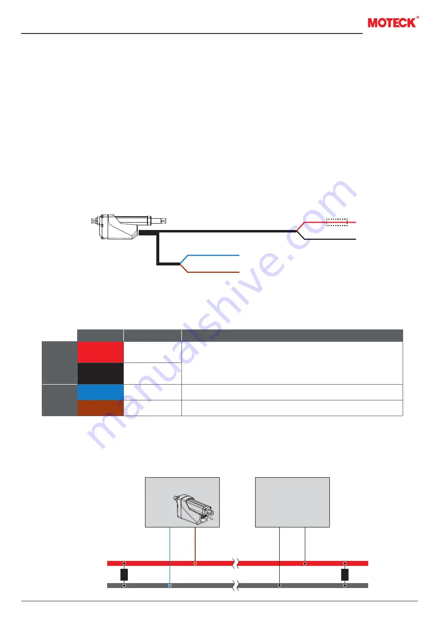
Wiring:
Wire definitions: J00
3.6.6.2
Connect CAN Bus SAE J1939 system
Please follow the wiring guidelines of ISO-11898 standard CAN 2.0B, protocol SAE J1939. The two ends of the CAN
High / Low harness should be connected with a 120Ω terminal resistor, as shown in the figure below.
CAN High
CAN Low
120Ω
R
120Ω
R
CAN Bus actuator
MK35
Blue
Brown
Fuse
V+
V-
CAN Low
CAN High
Connect Red to positive.
Connect Black to negative.
Do not swap the polarity.
Input voltage: 12/24V±20%
Power
cable
Description
Wire color
Black
Signal
cable
Brown
Blue
ECU
Red
Definition
V-
CAN High
CAN Low
V+
Remarks: All dashed lines (fuse) are connected by the customer.