SDY
12 The Interface Solution Experts
PC-Programmable Signal
Isolator/Converter with Display
Creating a Custom Linearization
Table
The SDY supports user-defined linearization of
both voltage and current inputs. Up to 85 input/
output points can be defined, and the user can
also specify the format and engineering units of the
output (viewable with the Configuration Program).
This section explains how to create a Custom
Linearization Table for downloading into SDY
memory.
The instructions assume that the Configuration
Program has been loaded successfully. Moore
Industries also suggests saving the initial settings
resident in the transmitter before making any
changes.
To create a Custom Linearization Table:
1. Attach the equipment listed in Table 1
as shown in Figure 2 and start the PC
Configuration Program.
Note:
It IS NECESSARY to connect a unit to the PC in
order to create a Custom Linearization Table.
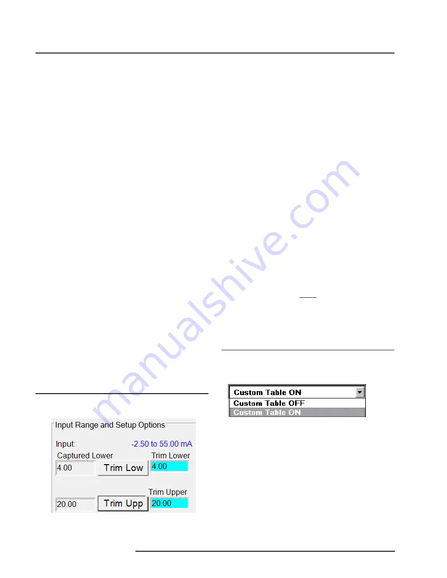
2. Use the pull-down menu to set “Linearization
ON”.
Figure 7.
Linearization must be set to ON to create a custom
table
3. Click on the “CustTable” (Customize
Linearization Table) button. This causes the
Configuration Program to change its upper-
right corner area to accommodate the table.
4. Use the table fields to set values for input
and output from the transmitter’s intended
application.
Use the Up, Down, Left, and Right arrow
keys on the PC keyboard to move the cursor
among the cells in the table.
Trimming the Input
Use this feature of the SDY to enhance the
accuracy of the transmitter by precisely matching its
actual input reading to its scaling of the either one
or two input points. Trim the input by following the
directions below:
1. Connect the transmitter to your PC using the
setup shown in Figure 2.
2. Click the radio button labeled “Input Trim On”.
3. Click “Start”, then “InpTrim”.
4. Select whether you will trim two points (upper
and lower) or just one point by clicking on the
appropriate radio button in the “Trim Pnts”
section.
5. In the “Trim Lower” and “Trim Upper” boxes,
type in the sensor’s value that you are
trimming.
6. Attach an input source to the transmitter.
Using a calibrated multimeter to determine
the current, set the input source to match the
“Trim Lower” value you have chosen. Click
“Trim Lower” and wait for it to capture the
value.
7. Using a calibrated multimeter to determine the
current, set the input source value to match
the “Trim Upper” value you have chosen.
Click “Trim Upper” and wait for it to capture
the value.
8. Click on the button labelled “QuiInTrim”, then
the “Stop” button, and finally the “Prog” button
to send the trim values to the transmitter.
Figure 6.
Trim Capture Box
Содержание SDY
Страница 22: ...SDY 22 The Interface Solution Experts PC Programmable Signal Isolator Converter with Display...
Страница 23: ...SDY The Interface Solution Experts 23 PC Programmable Signal Isolator Converter with Display...
Страница 24: ...SDY 24 The Interface Solution Experts PC Programmable Signal Isolator Converter with Display...


