36
Rev. 1.0
0012072012
TSM24P User Manual
+86-400-820-9661
5.5.6 Verify the Drive Current
The amount of drive current can be verified at any time during the tuning process to make sure the
current supplied to the motor is not being limited by the drive. If too much current is being required
changes may be made to the move profile. Select
Current
in one of the
Plot
selection lists and
repeat the move, from this the current can be evaluated.
5.5.7 Finishing up
If the TSM will only be operated in a
Velocity Control Mode
with a
Speed only
Control Type, the
tuning is complete. The Position Loop
(P Loop)
does not need to be tuned as it is not used. After
verifying the drive current, the
Notch Filter
may be the only setting still needing adjusting. See
section 5.8 on “Setting the Notch Filter”.
If the TSM will be operated in a
Position Control Mode,
proceed to section 5.6 ”Tuning the
Position Loop” below.
See Section 5.7 below on “Using Auto Trigger Sampling” for tuning the TSM while using an
external Pulse & Direction controller.
5.6 Tuning the Position loop
5.6.1 Entering a Sample Move
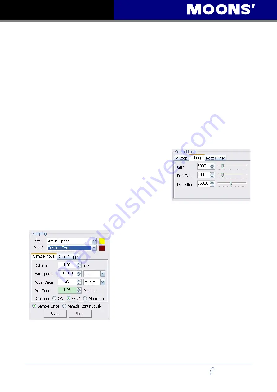
Select the
P Loop
tab in the
Control Loop
dialog section.
This will cause the
Sampling
to do moves that are based
on distance and operates the drive in the
Point to Point
Positioning mode.
Now the parameters for a
Position
based move can be
entered. There is one consideration that must be addressed
here. If the TSM is being operated in the
Position Control
Mode
with a
Pulse & Direction Digital Signal Type
setting
and being commanded by, for example, an external Pulse and Direction controller, the
Auto
Trigger
option may be used to capture and plot the move. See Section 5.6 on “Using the Auto
Trigger Sampling” for more details on this feature.
Plot 1 & Plot 2:
two different values can be selected for
viewing in the scope window, in this case
Actual
Speed
and
Position Error
are selected. For Position tuning these
are typical values.
Sample Move:
move profile values are entered in the
Sampling
section. This example sets a move
Distance
of
3.00 revs at a
Max Speed
of 20,000 rev/sec and an
Accel/
Decel
rate of 300 rev/s/s. In the window to the right of the
Sampling
data entry section the
Desired
Profile
will be
displayed. This provides a visual reference of what the
expected move will look like.
Plot Zoom:
the length of the plot values that are displayed
can be set from 1 to 5 times the profile length.
Dir:
the direction of the move can be set to
cw
,
ccw
or
alternate
. These directions refer to the motor shaft as viewed from the front of the motor.
Alternate
toggles the direction after each move. Start with a known direction before switching to
toggle.
Sample Once:
after the
Start
button is clicked, a single move is performed, the motor stops, and
the results will be displayed.


