background image

VFI33 Vent Free Gas Fireplace System

16

20307670

A. 

This appliance is equipped with a pilot which must be lit with built-in piezo ignitor while following these 

instructions exactly.

B. 

BEFORE OPERATING smell all around the appliance area for gas. Be sure to smell next to the floor 

because some gas is heavier than air and will settle on the floor.

WHAT TO DO IF YOU SMELL GAS:


  Turn off all gas to the appliance.


  Open windows. 


  Do not attempt to light any appliance.


  Do not touch any electric switch; do not use any phone in your building.


  Immediately call your gas supplier from a neighbor's phone. Follow the gas supplier's instructions.


  If you cannot reach your gas supplier, call the fire department.

C.  

Use only your hand to push in, or turn the gas control knob. Never use tools. If the knob will not push 

in or turn by hand, don't try to repair it. Call a qualified service technician. Force or attempted repair 

may result in a fire or explosion.

D. 

 Do not use this appliance if any part of it has been under water. Immediately call a qualified service 

technician to inspect the appliance and to replace any part of the control system and any gas control 

that has been under water.

 FOR YOUR SAFETY READ BEFORE LIGHTING 

LIGHTING PILOT FOR THE FIRST TIME  

INITIAL LIGHTING


Purge air from the supply line as follows: 


  Open main shutoff valve.


  Unscrew main pressure test point.


  Leave inlet test screw open until gas comes in.


  When gas is flowing, tighten inlet screw immediately. 

LEAK TESTING

1. Follow the pipe from the gas supply line connection to the gas valve. Check connection for leaks 

with soap and water mixture. 

2. Next check for gas leaks at the burner with soap and water mixture.
3.  Check the pilot for gas leaks with soap and water mixture.

OPERATING INSTRUCTIONS – MILLIVOLT

WARNING: If you do not follow these instruction exactly, a fire or explosion may result 

causing property damage, personal injury or loss of life.

WARNING: NEVER 

use open flame 

to check for gas leaks.

Содержание VFI33C(N/P)(V/I)

Страница 1: ...mmable vapors and liquids in the vicinity of this or any other appliance WHAT TO DO IF YOU SMELL GAS Do not try to light any appliance Do not touch any electrical switch do not use any phone in your building Leave the building immediately Immediately call your gas supplier from a neighbor s phone Follow the gas supplier s instructions If you cannot reach your gas supplier call the fire department ...

Страница 2: ... Instructions IPI 21 For Your Safety Read Before Lighting 21 What to Do If You Smell Gas 21 Operating Instructions 21 To Turn Off Gas 21 EcoLogic Control 22 Electrical Wiring Fan 23 Log Placement 24 Before You Begin 24 Cast Iron Grate Installation 24 Rock Wool Placement 25 Berkley Oak Logs 25 Place the Decorative Rock 26 Highland Oak Logs 27 Place the Decorative Rock 28 Kentucky Wildwood Logs 28 F...

Страница 3: ... away from furniture and draperies 2 Children and adults should be alerted to the hazard of high surface temperature and should stay away to avoid burns or clothing ignition 3 Young children should be carefully supervised when they are in the same room with the appliance 4 Do not place clothing or other flammable material on or near the appliance 5 Any safety screen or guard removed for servicing ...

Страница 4: ... under water 24 Never burn solid fuels in a fireplace where a unvented room heater is installed 25 Always have a fireplace screen in place when the appliance is in operation and unless other provisions for combustion air are provided the screen must have an opening s for induction of combustion air THIS APPLIANCE MAY BE INSTALLED IN AN AFTER MARKET PERMANENTLY LOCATED MANUFACTURED MOBILE HOME WHER...

Страница 5: ...nt of oxygen available in the room and shuts the gas log heater off if the oxygen level begins to drop below a satisfactory level The pilot can only be re lit when adequate fresh air is available THERMAL GENERATOR The millivolt gas log pilot is fitted with a millivolt generator to provide power for remote activation VFI33 CONTROLS GAS SPECIFICATIONS ORIFICE SIZE MODEL FUEL CONTROL MAX INPUT BTU h ...

Страница 6: ... this issue your fireplace has been designed with a cold climate pilot option which when active maintains a warmer temperature inside your firebox to make ignition faster and more efficient Operating your appliance in cold climate aka standing pilot mode will prohibit the need for multiple ignition attempts and will prevent the system from delaying start up or locking out To activate the cold clim...

Страница 7: ... on carpeting vinyl tile or other soft floor coverings It may however be placed on flat wood plywood particle board or other hard surfaces Be sure fireplace rests on a solid continuous floor or platform with appropriate framing for support and so that no cold air can enter from under the firebox Your vent free fireplace must be mounted to the floor or the fireplace hearth The millivolt controlled ...

Страница 8: ...ire width and depth of the base Mantel clearances The canopy supplied with the unit must be installed If a combustible mantel is installed It must meet the clearance requirements shown in Figure 7 FP2770 sidewall ceiling clearances 9 Minimum 9 Minimum 42 Minimum Figure 4 Sidewall and Ceiling Minimum Clearances FP2770 3 3 1 5 1 4 22 3 4 23 7 8 Figure 5a Dimensions for Installing in Masonry Fireplac...

Страница 9: ...ible projection To install the heater with a wooden mantel shelf or other combustible projection above first measure the heat resis tant material shown in Figure 6 CLEARANCES FP2772 mantel material No combustible materials within 8 of opening Hood Grate Figure 6 Measure Heat Resistant Material for Mantel Example Amantel may project from the wall a maximum of 21 2 at minimum of 8 above the opening ...

Страница 10: ...en by pushing screen frame panel up and out Figure 9 NOTE Fireplace screen must be removed to access log box and to install canopy Figure 10 Remove Fireplace Screen INSTALL CANOPY 1 Remove the fireplace screen as described in the previ ous section 2 Align canopy with the holes in the top frame assembly Figure 10 3 Install the three 3 screws in owner s manual packag ing which attach the canopy to t...

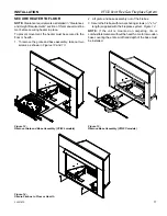
Страница 11: ... two screws as shown in Figures 12 and 13 INSTALLATION Figure 12 Remove Grate and Base Assembly VFI33L models Figure 13 Remove Base Assembly VFI33C models 2 Lift grate and base assembly out of the firebox 3 Secure the firebox with two anchoring screws 3 16 x 11 2 length supplied with the fireplace system Figure 14 NOTE If the unit is mounted on carpeting tile or combustible material without the he...

Страница 12: ...soap and water solution after completing connection DO NOT USE AN OPEN FLAME Check the gas pressure with the appliance burning and the control set to HIGH Open control access door on either side of unit to find valve and regulator referred to below Figure 16 Cord Protector Manual Gas Shutoff Recommended Outlet Positioned Vertical Stainless Flex Line Access Door for Gas Line WARNING Connecting dire...

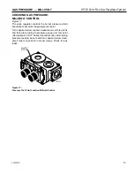
Страница 13: ...ressure test point Turn captured screw counter clockwise two or three turns and then place tubing to pressure gauge over test point Use test point OUT closest to control knob After taking pressure reading be sure and turn captured screw clock wise firmly to re seal Do not over torque Check for gas leaks FP2781 millivolt valve Test Port OUT FP2781 Figure 17 Pressure Test Point Location Millivolt Co...

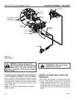
Страница 14: ...5 feet maximum length 2 At one end of the cable connect both wires to the wall switch or thermostat At the other end connect one wire to TP TH and one wire to TH or connect the wall switch thermostat to the two male 0 25 terminals on the left side of the unit The color of the wires does not matter ELECTRICAL WIRING MILLIVOLT FP2112a wiring diagram 8 09 Figure 18 Wiring Diagram Switch On Off Switch...

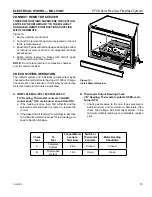
Страница 15: ...tch must face forward NOTE Do not place remote in combustion chamber only the remote receiver CHECK SYSTEM OPERATION The millivolt system and individual components may be checked with a millivolt meter having a 0 1000 mV range Conduct each check shown in chart below by connection meter test leads to terminals as indicated A COMPLETE MILLIVOLT SYSTEM CHECK A Reading Thermostat contacts CLOSED contr...

Страница 16: ...Force or attempted repair may result in a fire or explosion D Do not use this appliance if any part of it has been under water Immediately call a qualified service technician to inspect the appliance and to replace any part of the control system and any gas control that has been under water FOR YOUR SAFETY READ BEFORE LIGHTING LIGHTING PILOT FOR THE FIRST TIME INITIAL LIGHTING Purge air from the s...

Страница 17: ...NG PILOT Pilot Position Check for gas leaks in each of the following locations Pipe from the gas supply line connection to the gas valve Burner connections Field made joints gas shutoff valve Pilot Factory made joints Each joint or connection All joints on valve and control body LIGHTING PILOT FOR THE FIRST TIME OPERATING INSTRUCTIONS MILLIVOLT WARNING NEVER use open flame to check for gas leaks W...

Страница 18: ...er to ignite MAIN BURNER SWITCH This switch allows you to turn on and to turn off the main burner without using the gas valve knob is in the ON position to light the main burner Depress and turn knob clockwise to OFF position TO TURN OFF GAS Off Position FP3033 wall switch PILOT O F F P I L O T ON FP1935 control knob pilot O F F P I L O T O N PILOT FP1937 control knob on Pilot Position On Position...

Страница 19: ...sed with a wall switch wall mounted thermostat or IPI hand held remote control JUNCTION BOX WIRING 1 This should be done before framing the fireplace Wire the receptacle into an electrical circuit Wire with mini mum 60 C wire in accordance with prevailing codes 2 Remove the external junction box cover by removing the screw from the side of the outside firebox wall Junction box was installed at the...

Страница 20: ...g service Figure 22 IPI System Wiring Diagram IPI SYSTEM WIRING DIAGRAM ELECTRICAL INSTALLATION IPI WALL SWITCH INSTALLATION The wall switch wire connection is located off the wire harness coming out of the IPI Control Board The label is wired wall switch Connect the low voltage switch wires to the two 2 terminals labeled wall switch from the control board Run wire to desired location on wall Up t...

Страница 21: ...t the appliance and to replace any part of the control system and any gas control that has been under water FOR YOUR SAFETY READ BEFORE LIGHTING WARNING If you do not follow these instructions exactly a fire or explosion may result causing property damage personal injury or loss of lie TO TURN OFF GAS TO APPLIANCE 1 Turn Wall Switch to OFF 2 Turn Master Switch to OFF 3 Turn off all electrical powe...

Страница 22: ...r RED 1 time Trial Lockout One GREEN every 2 seconds until manual reset Flames Loss Lockout One RED GREEN every 2 seconds until manual reset AC Power On GREEN Solid REMOTE FUNCTION OPERATION ICON Fireplace On Press the ON button on the transmitter Fireplace Off Press the OFF button 3 times or hold the OFF button 3 seconds for memory off Flame Height Up Press the ON button once to turn on the firep...

Страница 23: ...ermostat Control Blower Motor Black FP2783 DIS wiring Figure 23 VFI Wiring Diagram Electrical power cord plug can be routed to exit the VFI33 on either the left side or the right side Remove cord protector from side of unit route power cord through hole opposite side Reinstall cord protector WARNING Never attempt to service heater while it is plugged in operating or hot Burns and or electrical sho...

Страница 24: ... of right side of grate into the I shaped slot on front right corner of unit After moving screw head to the bottom of the I slot insert the screw head on the back of the left side of grate into the keyhole slot on the left front of unit Figure 24 Cast Iron Grate B WARNING The positioning of the logs is critical to the safe and clean operation of this heater Sooting and other problems may result if...

Страница 25: ... ROCK WOOL PLACEMENT Before installing logs place rock wool in dime size pieces evenly over small burner ports starting in the rear of the burner going towards the front Avoid placing rock wool on slots on each side of rear burner and on large yellow flame ports on front of burner After covering small burner ports discard any excess rock wool Figure 25 Figure 26 Place Ember Chunk Log 1 Ember Chunk...

Страница 26: ...and locating blocks on logs 4 and 5 Figure 32 8 Place right top log 8 onto right rear 3 and right front 2 logs using locator on bottom of right top log Figure 32 Figure 32 Place Right Top Log 8 LG636 NB 18 24 log 8 Left Top Log 7 Right Top Log 8 PLACE THE DECORATIVE ROCK Optional volcanic rock may be placed around the unit on the floor of the firebox Be sure to avoid any areas on the burner itself...

Страница 27: ...nsure log is fully upright and does not tilt forward Slide 1 log ember chunk back to contact right rear log 2 Place front right log 2 on right pin located on burner and right grate bar Figure 34 After placing front right log ensure log is fully upright and tilting towards the back of the burner Right Front Log 2 Figure 37 Figure 36 Left Rear Log 4 Figure 35 Right Rear Log 3 4 Place left rear log 4...

Страница 28: ...gs 4 and 5 Figure 38 7 Place right top log 7 on right rear log 3 and right front log 2 using locators on the bottom of log 7 and locators on logs 2 and 3 Figure 38 8 Place small right front top log 8 on log 7 and log 2 using locating grooves on the bottom of log 8 and locating blocks on log 7 and log 2 Figure 39 LOG PLACEMENT LOG PLACEMENT LG1170 KW24 log 2 Log 2 Figure 41 LG1169 KW24 log 1 Log 1 ...

Страница 29: ...g 3 and on left grate bar LG1174a KW24 log 6 Log 6 Figure 45 Figure 44 LOG PLACEMENT LOG PLACEMENT 7 Place top right log 7 on the two 2 pins located on log 2 and log 1 Figure 46 Log 7 FIREGLASS PLACEMENT NOTE Two 2 bags of glass are supplied with the fireplace Both bags may be used to cover the entire floor and burner We advise against using additional glass as too much can cut off the proper amou...

Страница 30: ...ngement with any log If any yellow flame is contacting any log turn off log set and allow to cool Remove all logs and carefully rein stall following log placement instructions precisely Relight burner and check again for impingement of any flame on log If flame impingement cannot be eliminated contact your installer or dealer for assistance Flame impingement on logs may create soot and possible pr...

Страница 31: ...lier from a neighbor s phone Follow the gas supplier s instruc tions If you cannot reach your gas supplier call the fire department C Use only your hand to push in or turn the gas control knob Never use tools If the knob will not push in or turn by hand don t try to repair it Call a qualified service technician Force or attempted repair may result in a fire or explosion D Do not use this appliance...

Страница 32: ... out of the gas piping 7 With the control knob pushed in push in and release the piezo ignitor button to light the pilot 8 Continue pushing the control knob in for a further 60 seconds to prevent the flame detector from shut ting off the gas while the probe is warming up Release the control knob 9 Turn gas control knob counterclockwise to the ON position 10 After the pilot has been lit for one min...

Страница 33: ...ry for easy access to the pilot for example logs screens etc 2 Follow appropriate lighting instructions found previously Instead of pushing and releasing the piezo button light a match and hold the flame to the end of the pilot and ignite the pilot 3 After control knob has been released and pilot stays lit reinstall any items that were removed for pilot access 4 Call a qualified service technician...

Страница 34: ...ports Inspect ODS pilot for operation and accumulation of lint at air intake holes Verify flame pattern and log placement for proper operation Verify smooth and responsive ignition of main burner and rear burner CLEANING AND SERVICING PERIODIC CLEANING Refer to parts diagram for location of items discussed below Do not use cleaning fluid to clean logs or any part of heater Brush logs with soft bri...

Страница 35: ...Appliance shuts off during use 1 Not enough fresh air is available for ODS pilot to operate 2 Low line pressure 3 ODS pilot is partially clogged 4 Defective Thermopile 5 Restrictions in incoming air flow 1 Open window and or door for ventilation 2 Contact local gas company 3 Clean ODS pilot 4 Check pilot flame check wire connections check output should be 325 millivolts across TH TP and TP Termina...

Страница 36: ... burner orifice 2 Replace burner 3 Replace gas regulator Logs appear to smoke after initial operation 1 Vapors from paint or curing process of logs 2 Vapors or smoke continue after heater is run with damper or window open for several hours 1 Problem will stop after a few hours of operation Run the heater with the damper open if you have one or open a window for the first few hours 2 Log heater is ...

Страница 37: ...84K 4 Left Firebrick 1 20307263K Cinn 20307771K Col Red 5 Center Firebrick 1 20307264K Cinn 20307769K Col Red 6 Right Firebrick 1 20307262K Cinn 20307770K Col Red SURROUND 7 33 x 43 Small Black Surround 1 VFICFSS 7 36 x 50 Large Black Surround 1 VFICFSL OPTIONAL BLOWER COMPONENTS 8 Blower 1 26D0748K 9 Wiring Harness 1 26D0619 10 Blower Thermostat 1 23D6100 1 2 3 4 5 6 7 7 7 7 7 7 7 8 9 10 FIREBOX ...

Страница 38: ... 14D0503 14D0503 3 ODS Pilot Assembly 1 14D0473 14D0477 14D0473 14D0477 4 Piezo Wire 1 00K0632 00K0632 00K0632 00K0632 5 Control Valve 1 14D0467 14D0468 14D0467 14D0468 6 Pilot Regulator 1 14D0469 N A 14D0469 N A 7 Burner Injector 1 33D5040 58D0052 33D5040 58D0052 8 Female Valve Switch Wire 1 44D0500 44D0500 44D0500 44D0500 9 Male Valve Switch Wire 1 44D0501 44D0501 44D0501 44D0501 10 Knob Extende...

Страница 39: ...9 14D0476 26D2529 14D0476 7 ODS Module Wire 1 20301890 20301890 20301890 20301890 8 Control to ODS Module Wire 1 95E0120 95E0120 95E0120 95E0120 9 A C Adapter 1 95E0105 95E0105 95E0105 95E0105 10 Burner Injector 1 33D5040 58D0052 33D5040 58D0052 11 Pilot Regulator 1 14D0469 N A 14D0469 N A 12 Piezo Wire 1 20303256 20303256 20303256 20303256 ACCESSORIES Wall Switch Kit MVWS Wall Thermostat Kit WT H...

Страница 40: ...Log 1 81D0060 81D0084 4 Left Rear Log 1 81D0061 81D0085 5 Left Front Log 1 81D0062 81D0086 6 Middle Left Log 1 81D0063 81D0087 7 Left Top Log 1 81D0064 81D0088 8 Right Top Log 1 81D0065 81D0089 FOR MONESSEN BRANDED SYSTEMS REPLACEMENT PARTS ARE AVAILABLE THROUGH YOUR RETAILER WARNING Failure to position the parts in accordance with these diagrams or failure to use only parts specifically approved ...

Страница 41: ...5 Left Front Log 1 81D0014 81D0038 6 Left Top Log 1 81D0015 81D0039 7 Right Top Log 1 81D0016 81D0040 8 Right Front Log 1 81D0017 81D0041 2 3 4 5 6 7 8 1 BENEATH 7 FOR MAJESTIC BRANDED SYSTEMS REPLACEMENT PARTS REPLACEMENT PARTS ARE AVAILABLE THROUGH YOUR RETAILER WARNING Failure to position the parts in accordance with these diagrams or failure to use only parts specifically approved with this ap...

Страница 42: ... 3 1 20305904 4 Bottom front left log 4 1 20305905 5 Center left log 5 1 20305906 6 Center top log 6 1 20305907 7 Top right log 7 1 20305908 FOR MONESSEN OR MAJESTIC BRANDED SYSTEMS REPLACEMENT PARTS REPLACEMENT PARTS ARE AVAILABLE THROUGH YOUR RETAILER WARNING Failure to position the parts in accordance with these diagrams or failure to use only parts specifically approved with this appliance may...

Страница 43: ...ation instructions The Limited Lifetime Warranty will also be void if the appliance is not operated and maintained according to the operating instructions supplied with the appliance and does not extend to 1 firebox burner assembly damage by accident neglect misuse abuse alteration negligence of others including the installation thereof by unqualified installers 2 the costs of removal re installat...

Страница 44: ...149 Cleveland Drive Paris Kentucky 40361 www vermontcastingsgroup com ...

Отзывы: