background image

AS 914 TI 

User Manual

 49

2

10

4

a

c

d

e

b

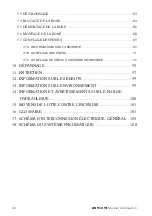
and gradually offsets the abrupt uneven thickness 
caused by the side ring.
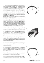
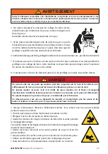
11 - Flap

. This is the part of the casing ply around the 

side ring and placed against the casing, to secure the 
ply and prevent it from slipping.

12 - Foot

. This is the innermost layer of the tread in 

contact with the belt, or if the latter is not present 
(conventional tyre) with the last casing ply.

13 - Shoulder.

 This is the outer part of the tread, be-

tween the corner and start of the sidewall.
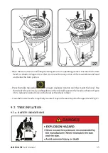
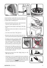
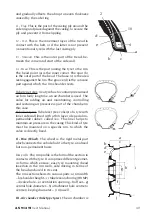
14 - Bead

. This is the part joining the tyre to the rim. 

The bead point (a) is the inner corner. The spur (b) 
is the outer part of the bead. The base (c) is the area 
resting against the rim. The groove (d) is the concave 
part against which the rim shoulder rests.

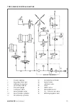
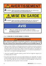
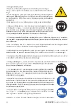
Tube type tyres. As a tyre has to contain pressurised 
air for a fairly long time, an air chamber is used. The 
valve for adding air and maintaining, controlling 
and restoring air pressure is part of the chamber in 
this case.
Tubeless tyres. Tubeless tyres consist of a tyre with 
inner sidewall lined with a thin layer of special im-
permeable rubber, called 

liner

. This liner helps to 

maintain air pressure in the casing. This kind of tyre 
must be mounted on a specific rim, to which the 
valve is directly fixed. 
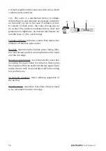
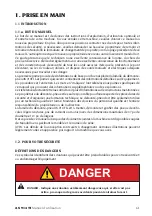
II - Rim (Wheel).

 The wheel is the rigid metal part 

which connects the vehicle hub to the tyre, on a fixed 
but non-permanent basis.
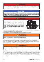
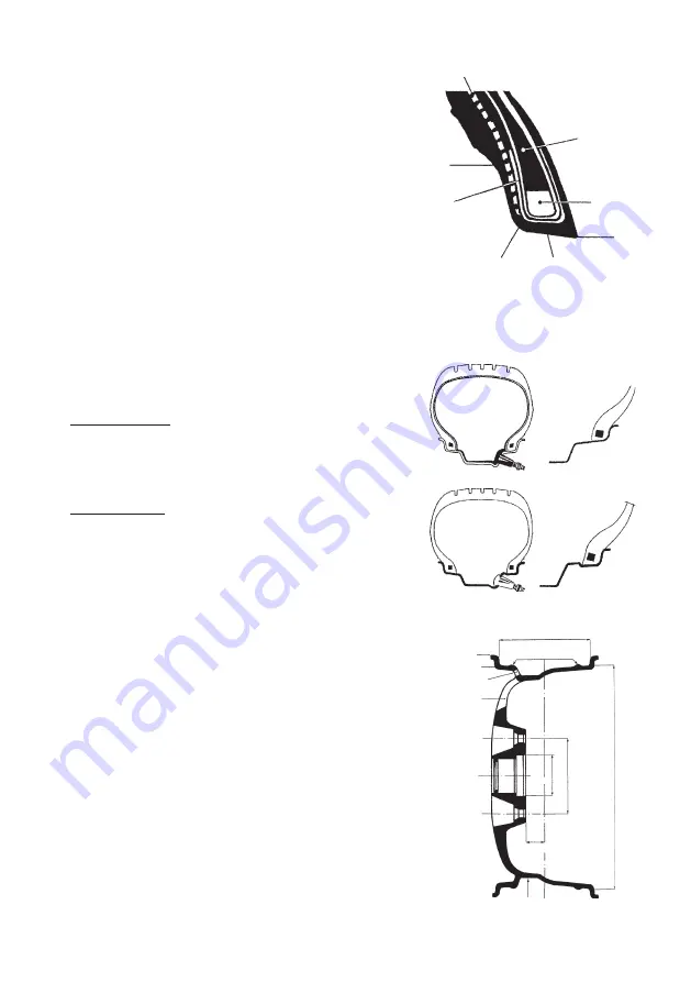
Rim profile. 

The rim profile is the form of the section in 

contact with the tyre. It comprises different geomet-
ric forms, which ensure: easy tyre mounting (bead 
insertion in the rim well); safe driving, in terms of 
the bead anchored in its seat.
The rim section shows its various parts: a) rim width 
– b) shoulder height – c) tubeless anchoring (HUMP) 
– d) valve hole – e) ventilation opening – f) off set – g) 
central hole diameter – h) attachment hole centre to 
centre i) keying diameter – j) rim well.

III - Air chamber (tube type tyres). 

The air chamber is 

f

g h

i

a

c

b

d

e

j

Содержание Aquila AS 914 TI

Страница 1: ...AS 914 TI Code 4 103170E 11 2017 Operator s manual Manuel d utilisation info mondolfoferro it www mondolfoferro it...

Страница 2: ...Tyre Changer is in optimum working order If you suspect that anything is not working properly or that a dangerous situation may exist immediately shut down the Tyre Changer and remedy any condition be...

Страница 3: ...entre Wheels Steel Jaw Internal External Clamping Bead Breaking Standard Wheels Low Profile Wheels Demounting Standard Wheels with Bead Lever and Plastic Sleeve Protector Full Seating of Mount Demount...

Страница 4: ...________________________________________________________ _____________________________________________________________________ _____________________________________________________________________ ___...

Страница 5: ...cial rim tyre considerations 18 1 4 intended use of the machine 18 1 5 employee training 18 1 6 pre use checks 18 1 7 during use 19 2 TRANSPORT STORAGE AND HANDLING 19 3 unpacking assembly 20 4 HOISTI...

Страница 6: ...YRES inflation 33 9 8 a Safety indications 33 9 8 b Inflating tyres 35 9 8 c Inflating tubeless tyres TI versions only 36 10 troubleshooting 39 11 maintenance 41 12 INFORMATION ABOUT SCRAPPING 43 13 e...

Страница 7: ...ipment procedures and maintenance Italics are used to refer to specific parts of this manual that provide additional information or explanation Thesereferencesshouldbereadforadditionalinformationtothe...

Страница 8: ...ep it with the machine in a safe place for future reference WARNING 1 If the use and maintenance procedures provided in this manual are not properly performed or the other instructions in this manual...

Страница 9: ...any tyre unless the tyre size molded into the sidewall matches the rim size stamped into the rim exactly or if the rim or tyre are defective Never exceed the tyre pressure recommended by the tyre man...

Страница 10: ...e on a cracked bent rusted worn deformed or damaged rim 15 If a tyre becomes damaged during the mounting process do not attempt to finish mounting Remove from the service area and properly mark the ty...

Страница 11: ...mptedbyusers 24 The user should understand all warning decals affixed to this equipment before operating 25 DO NOT lock the rim on the turntable during inflation 1 2 b DECAL PLACEMENT No Part Number D...

Страница 12: ...ANUFACTURED Mod V A kW Hz Ph bar7psi Port max DECAL MODEL SERIAL NUM BER 11 4 325629 DECAL ERGO LINE 12 35023276 DECAL SAFETY INSTRUC TIONS 13 35019966 DECAL INFLATING PEDAL 14 446388 DECAL CORRECT FE...

Страница 13: ...AS 914 TI User Manual 13 1 5 6 7 8 9 11 14 15 16 18 12 2 3 4 10 13 17 Danger warning decals part nr 35024870 Safety instructions...

Страница 14: ...Crushing hazard part nr 446431 Crushing hazard part nr 446442 EXPLOSION HAZARD Do not puncture Danger pressurised container part nr 425211A Risk of electrical shock part nr 3501700 Hand crushing haza...

Страница 15: ...as indicated on the general wiring diagram in this manual connect the machine to an industrial socket the machine must not be connected to domestic sockets An effective grounding connection is essent...

Страница 16: ...evelsandexposurelevels this cannot be used reliably to establish whether or not further precautions are necessary The factors which determine the level of exposure to which the operator is subject to...

Страница 17: ...of inflation jets 4 Only activate the air inflation jets if the rim securing device is locked in place and the tyre is properly clamped when possible 1 3 Special Rim Tyre Considerations Wheels equipp...

Страница 18: ...r leaning over Installing and removing rim wheels 3 The employer shall evaluate each employee s ability to perform these tasks and to service rim wheels safely and shall provide additional training as...

Страница 19: ...eight with packing kg 288 Machine storage and shipping specifications Temperature 25 55 C Do not stack other goods on top of the packing or damage may result NOTICE Handling To move the packing insert...

Страница 20: ...The machine comprises 2 main units fig 1d A body B column with internal tankandmountinghead arm Afterremovingthecolumn B it is advisable to place it in a horizontal position to prevent it from fallin...

Страница 21: ...move the plug and fi t the rubber hose M on connection O and tighten the hose clip N Fig 4 Open the bead breaker arm Q Fig 5 Fit the distance bush P over the bead breaker cylinder rod and close the be...

Страница 22: ...applicable safety regula tions including but not limited to those issued by OSHA Risk of Explosion or Fire Never use the machine in an area where it will be exposed to flammable vapours gasoline paint...

Страница 23: ...als and hand operated valves and levers This tyre changer has been designed exclusively for mounting and demounting tyres using the tools with which they are equipped as described in this manual The m...

Страница 24: ...ese conditions the operator can carry out monitor and check the outcome of all tyre change operations and take action in the case of any unforeseen events NOTICE RISK OF CRUSH INJURY Column tilting mu...

Страница 25: ...ation control pedal with three positions position 0 table stopped pedal depressed and held down with foot clockwise rotation pedal lifted and held up with foot counterclockwise rotation 10 Sliding cla...

Страница 26: ...TI User Manual 25 Pins for extensibile arm 26 Blade protection 11 8 OPTIONAL ACCESSORIES For a complete list of optional accessories supplied on request see the document ORIGI NAL ACCESSORIES FOR TIR...

Страница 27: ...solate the compressed air line by disconnecting the shutoff valve quick release connector fig 12 WARNING Avoid unintended machine movement or failure Use only original Mondolfo tools and equipment WAR...

Страница 28: ...annot be sold on these markets High performance wheels asymmetric curvature Fig 13 b SomeEuropeanwheelshaverimswithavery pronouncedcurvatureC exceptintheareaofthevalve hole A where the curvature is le...

Страница 29: ...hown in fig 15a and move the bead breaking shoe near the rim edge 15a 16 15 During the bead breaking operation you are advised to keep the turntable closed clamp gripper towards the centre NOTICE Pres...

Страница 30: ...nd re fitted only from the narrow side Press pedal to bring the sliding clamps to the outside of the table Fig 18 if you wish to clamp the rim on the outside as shown in Figure 18 recommended for allo...

Страница 31: ...AS 914 TI User Manual 31 Press pedal in order to clamp the wheel with the sliding clamps see fig 20 to regulate turntable clamping capacity 10 20 13 23 14 24 min 17 20...

Страница 32: ...ng the wheel Position the mount demount head against the edge of the rim Immobilize vertical movement of the head with lever Fig 20a Turn knob 5 in order to adjust the mount demount head as illustrate...

Страница 33: ...clockwise The upper bead will be automatically guided up and over the edge of the rim Repeat the procedure for the bottom bead Fig 23 21 22 23 B A 20c Distance A is created automatically when lever i...

Страница 34: ...rim and geometrical size keying diameter cross section width Off Set and shoulder profile before mounting AVOID PERSONAL INJURY OR DEATH Also check that rims are not deformed that their fixing holes h...

Страница 35: ...t head and below the front portion Press the table top pedal to begin clockwise rotation and thus mount the bead Use the wheel s drop centre by pushing down on the sidewall opposite the head as shown...

Страница 36: ...roperly lubricated with an approved mounting paste Safety goggles with plain lenses and safety footwear must be worn Don t Lock the rim on the turntable during inflation Remove valve stem core if not...

Страница 37: ...dB A may occur Wear hearing protection devices EXPLOSION HAZARD An exploding tyre and rim may be propelled upward and outward with enough force to cause serious injury or death Do not mount any tyre...

Страница 38: ...es of rim profiles for mounting without a camera in fig 31b From the position of the centring ridges check that the beads are properly positioned on the rim otherwise deflate the tyre break the beads...

Страница 39: ...oldthetyrewithyourhandsandlift it until there is a slight gap between the lower bead and bottom edge of the rim in order to close the upper beadandthetopoftherim fig 32d Fully press the inflation peda...

Страница 40: ...exceed the manufacturer s maximum pressure as stated on the sidewall of the tyre when seating beads If tires being mounted require more than the tire manufacturer s maximum bead seating pressure and t...

Страница 41: ...Tabletoprotatepedaldoes not return to its home centre position Control spring broken Change control spring Beadbreakerandtabletop rotate pedals do not return to their home positions Pedal return sprin...

Страница 42: ...ounts or mounts tires with difficulty Insufficient belt tension Adjust belt tension or change it Vertical slide lifts off too much or too little from the rim Clamping plate not ad justed Adjust plate...

Страница 43: ...up with lubricant disconnect the machine from the compressed air supply line Mondolfo declines all liability for claims deriving from the use of non original spa res or accessories NOTICE The purpose...

Страница 44: ...utomatic condensation drain system therefore in condi tions of normal use special maintenance is not required The condensate may however be drained manually at any time fig 32d Normally the cups do no...

Страница 45: ...e product and on this page reminds the user that the product must be disposed of properly at the end of its life This prevents the inappropriate disposal of the substances which this product contains...

Страница 46: ...use of hydraulic fluid Avoid contact with the skin Avoid the formation or spreading of oil mists in the atmosphere The following fundamental health precautions must therefore be adopted avoid spatters...

Страница 47: ...he rim wheel III the air chamber in tube type tyres IV pressurised air The tyre must withstand a load ensure driving power steer the vehicle aid handling and braking aid vehicle suspension I Tyre The...

Страница 48: ...independent rigidities so during rolling sidewall flexure is not transmitted to the tread 4 Sidering Thisisametalringcomprisingseveralsteel strands The casing plys are secured to the side ring 5 Belt...

Страница 49: ...e valve for adding air and maintaining controlling and restoring air pressure is part of the chamber in this case Tubeless tyres Tubeless tyres consist of a tyre with inner sidewall lined with a thin...

Страница 50: ...d the base c the outer lining Tubeless Inflator Inflation system that makes the inflation of tubeless tyres easier Beading Operation which takes place during infla tion and ensures perfect centring be...

Страница 51: ...AS 914 TI User Manual 51 115 230V 1Ph Tyre changer XS1 Power supply socket QS1 Inverter M1 Motor C1 Capacitor R1 Resistance 17 GENERAL ELECTRIC LAYOUT DIAGRAMS...

Страница 52: ...50 60Hz XS1 L1 N SQ3 XB1 SQ1 SQ2 M1 R T S 1 2 3 4 U V W MARRONE NERO AZZURRO GRUPPO MOTORE MOTOR UNIT GRUPPO COMANDI CONTROL SWITCH XS1 Power supply socket AP1 Single two speed motor motor M1 Motor SQ...

Страница 53: ...AS 914 TI User Manual 53 3Ph Tyre changer XS1 Power supply socket QS1 Inverter M1 Motor...

Страница 54: ...coupling 2 Regulator filter unit 3 Inflation foot pedal 5 Air release button 6 Pressure gauge 8 Table top valve 9 Bead breaker valve 10 Bead breaker cylinder 11 Rh table top cylinder 12 Lh table top c...

Страница 55: ...se button 6 Pressure gauge 8 Table top valve 9 Bead breaker valve 10 Bead breaker cylinder 11 Rh table top cylinder 12 Lh table top cylinder 18 Swivel valve 19 Air blast valve 20 Tank 21 Relief valve...

Страница 56: ...en bon tat de marche Si vous pensez que quelque chose ne fonctionne pas bien ou qu il y a une situation dangereuse arr ter le d monte pneu imm diatement et rem dier la situation avant de poursuivre Si...

Страница 57: ...reuse de la jante invers e Mors internes en acier blocage ext rieur D talonnage Pneus classiques Pneus profil bas D montage Pneus de base avec talon et protecteur de plastique Mise en place compl te p...

Страница 58: ...__________________________________________________________________ _____________________________________________________________________ _______________________________________________________________...

Страница 59: ...E PNEUS 71 1 4 UTILISATION PR VUE DE LA MACHINE 71 1 5 FORMATION DES EMPLOY ES 72 1 6 V RIFICATION AVANT L UTILISATION 72 1 7 PENDANT L UTILISATION 72 2 TRANSPORT ENTREPOSAGE ET MANUTENTION 73 3 D BAL...

Страница 60: ...it 89 9 7 b Gonflage des pneus 91 9 7 c Gonflage de pneus chambre incorpor e 92 10 D PANNAGE 95 11 ENTRETIEN 97 12 INFORMATION SUR LES REBUTS 99 13 INFORMATION SUR L ENVIRONNEMENT 99 14 INFORMATION ET...

Страница 61: ...roc dures et l entretien Les mots en italiques font r f rence aux parties sp cifiques de ce manuel qui procurent des informations suppl mentaires ou des explications Cesr f rencesdevraient treluesafin...

Страница 62: ...erver avec la machine dans un endroit s r pour une consultation ult rieure AVERTISSEMENT 1 Silesproc duresd utilisationetd entretienfourniesdanscemanuelnesontpascorrectement effectu es ou les autres i...

Страница 63: ...orrespond exactement la taille de la jante grav sur la jante ou si la jante ou le pneu est d fectueux Ne jamais d passer la pression du pneu recommand par le fabricant Ce d monte pneu n est pas un dis...

Страница 64: ...dysfonctionnement 14 NE JAMAIS installer ou gonfler des pneus qui sont coup s endommag s pourris ou us s NE JAMAIS installer un pneu sur une jante f l e pli e rouill e us e d form e ou endommag e 15 S...

Страница 65: ...us qualifi e L employeur est respon sable de d terminer si un employ est qualifi pour effectuer des r parations sur la machine en toute s curit ou si la r paration devrait tre faite par les utilisateu...

Страница 66: ...I COSTRUZIONE MANUFACTURED Mod V A kW Hz Ph bar7psi Port max AUTOCOLLANT MOD LE ET NUM RO DE S RIE 11 4 325629 AUTOCOLLANT ERGO LINE 12 35023276 AUTOCOLLANT CONSIGNES DE S CURIT 13 35019966 AUTOCOLLAN...

Страница 67: ...AS 914 TI Manuel d utilisation 67 1 5 6 7 8 9 11 14 15 16 18 12 2 3 4 10 13 17 AUTOCOLLANT DANGER AVERTISSEMENT pi ce n 35024870 Consignes de s curit...

Страница 68: ...sque d crasement pi ce n 446431 Risque d crasement pi ce n 446442 DANGER D EXPLOSION Ne pas perforer Danger contenant pressuris pi ce n 425211A Risque d lectrocution pi ce n 3501700 Risque d crasement...

Страница 69: ...selon le calibre indiqu dans le sch ma de branchement g n ral dans ce manuel brancherlamachine unepriseindustrielle lamachine ne doit pas tre branch e des prises domestiques Une connexion de mise la...

Страница 70: ...anger Bien qu il existe une relation entre les niveaux d missions et les niveaux d exposition ceci ne peut pas tre utilis de mani re fiable pour tablir si d autres pr cautions sont n cessaires Les fac...

Страница 71: ...ver le gonflage par jet que pour coller le talon 3 Purger le syst me d alimentation avant de d brancher le tuyau ou les autres compo santes pneumatiques L air est stock dans un r servoir pour le gonfl...

Страница 72: ...jours rester l cart du d monte pneu lors du gonflage et de l inspection de la roue apr s le gonflage ne jamais se pencher dessus Poser et d monter les roues 3 L employeur doit valuer la capacit de cha...

Страница 73: ...g Sp cifications pour l entreposage et l exp dition de la machine Temp rature 25 55 C Ne pas empiler d autres marchandises sur le dessus de l emballage ou des dommages pourrait survenir AVIS Manutenti...

Страница 74: ...neestcompos ede 2 l ments principaux Fig 1d A b ti B colonne avec un r servoir interne et une t te de montage et un bras Apr savoirenlev lacolonne B il est recommand de la placer en position hori zont...

Страница 75: ...l attache N du tuyau Fig 4 Ouvrir le bras du d talonneur Q Fig 5 Monter la douille entretoise P sur l axe du cylindre du d talonneur fermer le bras du d talon neur en ins rant la tige du cylindre dans...

Страница 76: ...e jamais utiliser la machine dans un endroit o elle sera expos e des vapeurs inflammables essence diluants de peinture solvants etc Ne jamais installer cette machine dans un endroit ferm ou au sous so...

Страница 77: ...r l op rateur manuellement par des p dales et des vannes et leviers Ce d monte pneu est con u uniquement pour monter et d monter les pneus utilisant les outils fournis comme d crits dans ce manuel Cet...

Страница 78: ...iller et contr ler le r sultat de toutes les op ration de changements de pneus et prendre des mesures dans le cas de tout v nements impr vus AVIS RISQUE DE BLESSURE PAR CRASEMENT L inclinaison de la c...

Страница 79: ...de rotation du plateau trois positions position 0 arr t plateau p dale appuy e et maintenue press e par le pied rotation dans le sens horaire p dale soulev e et maintenue soulev e par le pied rotation...

Страница 80: ...d utilisation 25 Axe pour bras extensible 26 Lame de protection 11 8 ACCESSOIRES EN OPTION Pour une liste compl te d accessoires au choix fournis sur demande voir le document ACCESSOIRES ORIGINALES P...

Страница 81: ...conduite d air comprim en d branchement la vanne d arr t raccord connexion rapide Fig 12b AVERTISSEMENT viter tout mouvement impr vu de la machine ou toute chute Utiliser seulement les outils et l qui...

Страница 82: ...dans ces march s Rouesdehauteperformance courbureasym trique Fig 13 b Certainesroueseurop ennesontdesjantesavecune courbure C tr s prononc e l exception de la zone A de l ouverturedelavalveo lacourbur...

Страница 83: ...ustr e sur la Fig 15a et d placer le sabot du d talonneur pr s du bord de la jante 15a 16 15 Pendant le d talonnage il est recommand de fermer le plateau blocage int rieur vers le centre AVIS Appuyer...

Страница 84: ...nt s seulement du c t troit Appuyer sur la p dale pour amener les mors coulissants vers l ext rieur de la table Fig 18 sivoussouhaitezposerlajante l ext rieur comme illustr sur la Fig 18 recommand pou...

Страница 85: ...914 TI Manuel d utilisation 85 Appuyer sur la p dale pour agripper la jante avec les mors coulissante voir la Fig 20 pour r guler la capacit de serrage de la table tournante 10 20 13 23 14 24 min 17...

Страница 86: ...tionner la t te de montage d montage contre le rebord de la jante Bloquer le mouvement vertical de la t te avec le levier Fig 20a Tourner le bouton de pivot 5 afin d ajuster la t te de montage d monta...

Страница 87: ...retournerdanslesens horaire Le talon sup rieur est automati quement guid en haut et par dessus le rebord de la jante R p terlaproc durepourletaloninf rieur Fig 23 21 22 23 B A 20c La distance A est cr...

Страница 88: ...t de monter VITER LES BLESSURES OU LA MORT V rifier galement que les jantes ne sont pas d form es que les trous de fixation ne sont pas devenus ovale qui ne sont pas souill s ou rouill s et qu ils n o...

Страница 89: ...sur la paroi lat rale oppos e la t te voir la Fig 26 pour r duire la force de tension sur le bourrelet lors de la rotation de la roue Une fois le talon inf rieur compl tement mont r p ter les m mes t...

Страница 90: ...sverresclairesetdeschaussuresdes curit doivent treport es Ne pas bloquer la jante sur le plateau pivotant durant le gonflage Retirer le corps de valve si ce n est d j fait Brancher le tuyau de gonflag...

Страница 91: ...auditifs DANGER D EXPLOSION Un pneu mont sur une jante qui explose peut tre propuls vers le haut et l ext rieur avec suffisamment de force pour pourrait causer des blessures graves ou voire la mort Ne...

Страница 92: ...tournerles PAULEMENTS de la jante voir les mod les de profil de jante pour un montage sans une cam ra dans la Fig 31b De la position des nervures de centrage v rifier que les talons sont bien position...

Страница 93: ...ever l obus de valve et brancher le connecteurDoyfedutuyaudegonflage au corps de valve Fig 32d Tenir le pneu avec vos mains et soule ver jusqu il y a un l ger cart entre le talon inf rieur et le rebor...

Страница 94: ...GER D EXPLOSION Ne pas d passer la pression maximale indiqu e par le fabricant de pneus sur le flanc pendant le collage des talons Si les pneus mont s exigent plus de pression que ce que le fabricant...

Страница 95: ...le moteur La p dale du plateau ne revient pas sa position de repos centre o Ressort de commande cass o Remplacer le ressort de commande Lesp dalesdud talloneur etduplateaunereviennent pas leurs posit...

Страница 96: ...is sants us es o Remplacer le cylindre du plateau o Remplacer les pointes des mors coulissants Le plateau d monte ou monte les pneus difficile ment o Tension insuffisante sur la courroie o Tendre la c...

Страница 97: ...us pression Avant de faire l entretien ou le remplissage de lubrifiant d brancher le circuit d air comprim de la machine MONDOLFO d cline toute responsabilit pour les r clamations d coulant de l utili...

Страница 98: ...r gulateur FR estdot d unsyst meautomatiquepourl vacuationdelavapeurd eau condens e donc dans des conditions d utilisation normales aucun entretien n est n cessaire tout moment il est possible d effec...

Страница 99: ...iques ne doivent jamais tre dispos s avec les d chets m nagers mais treachemin sdansuncentredetris lectifquisechargeradeleurtraitement Le symbole de la poubelle barr e appos sur le produit et illustr...

Страница 100: ...limin comme pr vu par la loi Pr cautions prendre pour l utilisation de fluide hydraulique viter tout contact avec la peau viter la formation ou la diffusion de brouillards d huile dans l atmosph re Le...

Страница 101: ...se de I du pneu II de la jante roue III delachambre air pourlespneus chambre air IV air comprim Le pneu doit supporter une charge assurer une puissance d entra nement tourner le v hicule aider la man...

Страница 102: ...s stable et emp cher un mauvais d placement de circulation de la bande de roulement dans la zone de contact avec le sol la carcasse et la sous chapesontrenforc esparunestructureannulaire g n ralementa...

Страница 103: ...ext rieure de la bande de roulement entre le coin et le d but du flanc 14 Talon Il s agit de la partie permettant le contact entre le pneu et la jante Le point a du talon est le coin int rieur L ergo...

Страница 104: ...tif m canique pour gonfler d gonfler le pneu et contenir la pression d air dans la chambre air oupneudanslecasdepneus chambre incorpor e Ilestcompos detroisparties lecapuchon a pourprot gerlem canisme...

Страница 105: ...AS 914 TI Manuel d utilisation 105 XS1 Prise d alimentation QS1 Inversseur M1 Moteur C1 Condensateur R1 R sistance 17 SCH MA D INTERCONNEXION LECTRIQUE G N RAL D monte pneu 115 230 V 1 Ph...

Страница 106: ...15V 50 60Hz XS1 L1 N SQ3 XB1 SQ1 SQ2 M1 R T S 1 2 3 4 U V W MARRONE NERO AZZURRO GRUPPO MOTORE MOTOR UNIT GRUPPO COMANDI CONTROL SWITCH XS1 Prise d alimentation AP1 Moteur un deux vitesses M1 Moteur S...

Страница 107: ...AS 914 TI Manuel d utilisation 107 D monte pneu 3 phases XS1 Prise d alimentation QS1 Inversseur M1 Moteur...

Страница 108: ...de l unit de filtre 3 P dale de gonflage 5 Bouton d vacuation de l air 6 Manom tre 8 Valve plateau 9 Valve du d talonneur 10 Cylindre du d talonneur 11 Rh Cylindre du plateau 12 Lh Cylindre du platea...

Страница 109: ...Manom tre 8 Valve plateau 9 Valve du d talonneur 10 Cylindre du d talonneur 11 Rh Cylindre du plateau 12 Lh Cylindre du plateau 18 Valveorientableavec croudeblocage 19 Soupape air comprim 20 R servoi...

Страница 110: ...COMIM Cod 4 103170E 11 2017...

Отзывы:

Похожие инструкции для Aquila AS 914 TI