


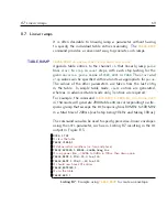


8.3 Digital I/O
61
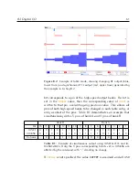
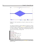
Figure 8.2:
Example of table mode, showing changing
RF
output (blue,
lower trace) and synchronised
TTL
output (red, upper trace) generated by
the example in Listing 8.2.
bit corresponds to a pin of the high-speed output banks.
If a bit is
set in the
IOMASK
value,
then the corresponding value of
IOSET
is
written to that pin, overwriting any previous value.
This allows all
pins of both high-speed banks to be changed in each table entry, or
only a subset of the pins.
Table 8.1 demonstrates an example that
simultaneously writes 5 pins of bank A and 4 pins of bank B.
Bank B
Bank A
Bit
16
15
14
13
12
11
10
9
8
7
6
5
4
3
2
1
IOSET
0
0
1
0
1
1
1
1
1
0
0
1
0
0
1
1
IOMASK
0
1
0
0
1
1
0
1
1
1
1
0
1
0
1
0
Outcome
-
0
-
-
1
1
-
1
1
0
0
-
0
-
1
-
Table 8.1:
Example of simultaneous output using
IOSET0x2F93
and
IO-
MASK0x4DEA
. Only the 9 pins corresponding to bits set in
IOMASK
are
affected by the command, with “-” denoting no change.
If
IOMASK
is not specified, the value
0xFFFF
is assumed and all
HSB
Содержание ARF021
Страница 1: ...Agile RF Synthesizer AOM driver ARF021 ARF421 XRF021 XRF421 Version 1 5 0 Rev 6 ...
Страница 4: ...ii ...
Страница 10: ...viii Contents ...
Страница 26: ...16 Chapter 3 Communications ...
Страница 44: ...34 Chapter 5 External modulation ...
Страница 50: ...40 Chapter 6 PID stabilisation ...
Страница 64: ...54 Chapter 7 Digital I O ...
Страница 100: ...90 Chapter 9 Advanced table mode XRF ...
Страница 128: ...118 Appendix C Command language ...
Страница 133: ......


