


XVC-100
Text Display PLC
Device Description XVC-100
Commissioning
Subject to technical modifications
Doc No. 92 23 100000 (06/2002)
© by Moeller GmbH
24
5.9 C
ONNECTION OF THE ANALOG INPUT
/
OUTPUT
- C
ONNECTOR
X 4
Connector Assignment for X 4
Connector X 4 - analog input / output
13-pole, WAGO multi-connector system MINI, RM 3.5 mm,
734-143
Counterpart: WAGO 734-113
Pin No.
Assignment Function
1
AI0
Analog voltage input 0
2
0-20mA
Analog current resistor 0
3 0V
Signal
GND
4
AI1
Analog voltage input 1
5
0-20mA
Analog current resistor 0
6 0V
Signal
GND
7
AQ0
Analog voltage output 0
8 0V
Signal
GND
9
AQ1
Analog voltage output 0
10 0V
Signal
GND
11
Uref
4.096VDC reference output (1mA)
12
0V
Signal Ground (ground potential)
13
0V
Signal Ground (ground potential)
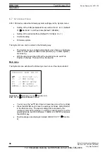
X 4
input / output level
Function: Analog Input
The analog inputs can be used for measuring and processing voltages and
currents. The evaluation of the analog value is processed via the same
terminal pin – the voltage input is changed to a current input by connecting
a parallel resistor. The diagram below shows the structure of the analog
input.
Voltage Input: The input range is 0 to +10VDC
The
input
resistance
is
1M
Ω
Current Input: The input range is 0 to +20mA
The
current
measuring
resistance
R
is 500
Ω
The A/D converter has a 10-bit resolution (LSB = 9.766mV)
The analog inputs are not isolated.
The connections must be shielded. The shield
connections must be grounded on the housing.
Mean analog input values are automatically determined
from the 8 most recent measured values. (arithmetic
mean)
+ IA0_U
+ IA0_I
0V
=
R
1 13
For Immediate Delivery call KMParts.com at (866) 595-9616


