

01/08 AWB2190-1430GB
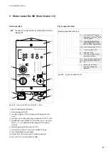
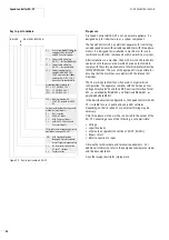
Setting the functions with DIP
switches/jumpers
81
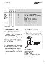
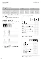
Activate phase reversal switch (pole 7)
Table 14: Phase reversal and reversing function
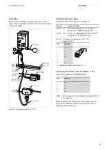
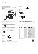
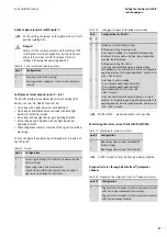
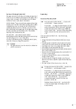
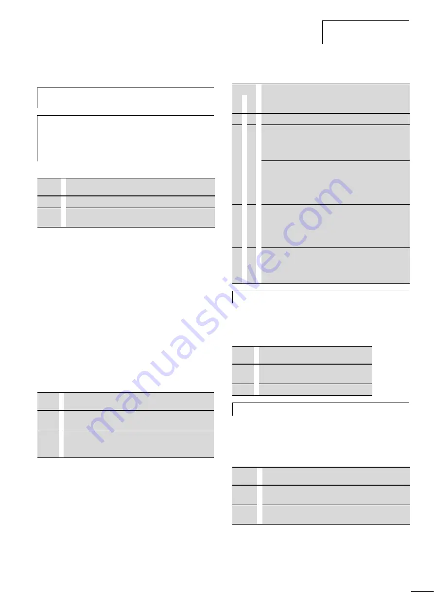
Configure external outputs (pole 5 – 6, 8)
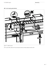
The RA-MO provides two external inputs for connecting light
barriers, sensors, etc. Add-on functions are:
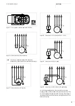
• Quick stop with a light barrier for both directions
• Quick stop and interlocked manual mode with both light
barriers for clockwise rotation
• Quick stop with one light barrier per operating direction
• Interlocked manual operation with one light barrier per
operating direction
• When using break contacts, inversion of the signals for internal
processing.
You can configure the external inputs through pins 5, 6 and 8 of
the DIP switch:
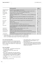
Table 15: Sensors
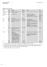
Table 16:
Setting quick stop and interlocked manual mode
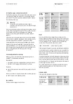
Monitoring the lower current limit with RA-MO24V
Table 17: Monitoring the lower current limit
Diagnostic status through AS-Interface
®
parameter
channel
Table 18: Diagnostic status through AS-Interface
®
parameter channel
h
For this setting, the jumper on the right must be in its left
position (
a
fig. 85).
j
Danger!
Safety risk! The jumper positions and the setting of DIP
switch pole 7 must be changed only by trained persons
and only in accordance with this manual. Incorrect
settings will reverse the operating direction.
pole 7
Configuration
0
Reversing starter (factory setting)
1
Reversing starters and phases L1 and L3 reversed (phase
reversal)
pole 5
Configuration
0
Sensor signals through AS-Interface®, no add-on function
(factory setting)
1
When using sensors with break contacts:
Signals are inverted for internal processing; the original
signals are sent through AS-Interface®.
Pole
Configuration for RA-MO…
6
8
0
0
No add-on function (factory setting)
1
0
With jumper setting Reversing starter:
Quick stop, I3 enabled. I3 is assigned to both operating
directions, I4 has no add-on function; typical application
example: chain discharger
With jumper setting DOL starter:
Quick stop and interlocked manual operation (edge-
controlled only), I3 and I4 enabled. I3 and I4 are assigned to
operating direction FWD; typical application: vertical sorter
with > 360° eccentric
0
1
Quick stop, I3 and I4 enabled.
I3 is assigned to operating direction FWD,
I4 is assigned to operating direction REV;
Typical application: Vertical sorter with
< 360° eccentric
1
1
Quick stop and interlocked manual operation, I3 and I4
enabled. I3 is assigned to operating direction Forward, I4 to
operating direction Reverse; typical example: Vertical sorter
with < 360 ° eccentric
h
With RA-MOL… manual operation is not possible.
pole 9
Configuration
0
Monitoring of lower current limit disabled
(factory setting)
1
Monitoring of lower current limit enabled
h
In 400 V models current monitoring is always enabled.
pole 10
Configuration
0
Diagnostic status through AS-Interface
®
parameter channel
and I/O error signal disabled (factory setting).
1
Diagnostic status through AS-Interface
®
parameter channel
and I/O error message enabled.
Содержание Rapid Link
Страница 10: ...01 08 AWB2190 1430GB 6 ...
Страница 40: ...01 08 AWB2190 1430GB 36 ...
Страница 48: ...01 08 AWB2190 1430GB 44 ...
Страница 70: ...01 08 AWB2190 1430GB 66 ...
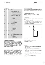
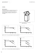
Страница 145: ...01 08 AWB2190 1430GB Parameterization with DrivesSoft 141 Figure 134 Example acceleration time ...
Страница 146: ...01 08 AWB2190 1430GB 142 ...
Страница 162: ...01 08 AWB2190 1430GB 158 ...