


Motor starter RA-MO
(from Version 3.0)
01/08 AWB2190-1430GB
78
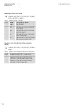
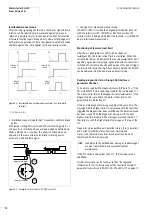
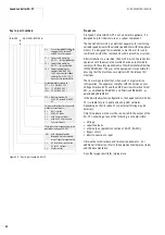
Interlocked manual mode
After the rising signal edge of I3 or on a continuous signal forward
rotation can be selected only in automatic operation; manual
selection is possible only for reverse operation. Manual selection
of forward rotation is possible again only after a falling edge at I3
during reverse operation or after a changeover to automatic mode
and back again). The same applies for I4 and reverse rotation.
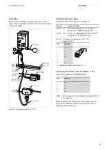
Figure 83: Interlocked manual operation (example: I3 and forward
rotation)
a
13.5 ms
g
5 ms
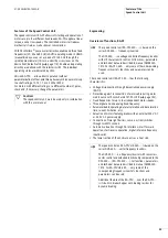
• Interlocked manual mode for 360° movements with two break
points:
With jumper setting DOL starter and DIP switch setting pole 6 = 1
and pole 8 = 0 interlocked manual mode is edge-controlled only.
When a break point is reached, this allows continued manual
operation in the same direction by briefly switching over to
automatic mode and back again.
• LED signal on interlocked manual mode:
LED FWD or REV is lit when the assigned direction has been set
with the selector switch. LED FWD or REV flashes when the
selector switch is being operated but the contactor is switched off
due to interlocked manual mode.
Monitoring of lower current limit
After the assigned jumper or DIP switch has been set
(
a
figure 85), the lower current limit is monitored. When the
current drops below 25 percent of the set value (
a
table 13 auf
page 80), a group error message is generated and the contactor is
switched off. Current values above 30 percent of
I
n
do not trigger
lower current level monitoring. After a Reset command the RA-MO
can be operated in both manual and automatic mode.
Reading diagnostic status through AS-Interface
®
parameter channel
To be able to read out the diagnostic status (DIP pole 10 = 1) the
PLC with WRITE P must send the parameter bit combination 111.
The motor starter returns the diagnostic status (
a
table 11). If no
diagnostic data is available, the motor starter returns the
parameter bit combination 111.
If two or more diagnostic messages apply at the same time, the
message with the highest priority is displayed until the fault that
triggered the diagnosis has been rectified and the Reset command
has been issued. Then the diagnostic message with the next
highest priority is displayed. The messages are listed inorder of
their priority, with the highest-priority message at the top of the
list.
Diagnostic messages Manual Operation (status_local_operation)
and Current Tresholds (status_overload_warning and
status_load_indication) are reset automatically and do not
therefore need a Reset command.
If the PLC sends a value other than 111, the returned value is
undefined.
Further information can be found at section “Background
information for PLC technicians about the function principle of
parameter transmission in RA-MO, RA-SP and RA-IN” on page 11.
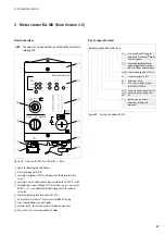
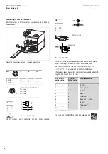
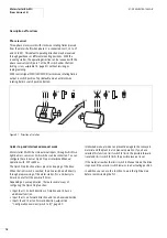
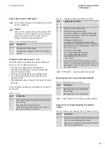
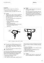
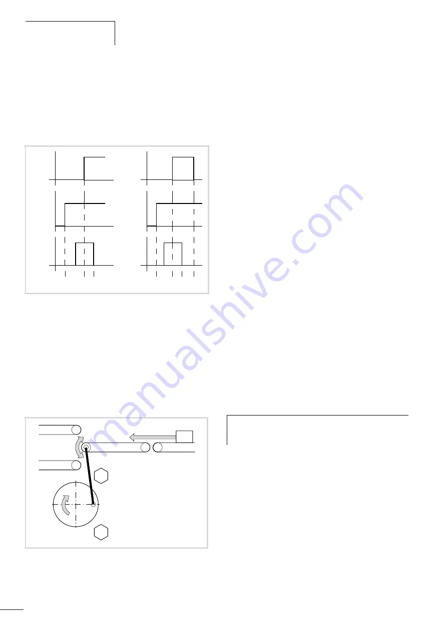
I3
I3
Selector
switch
H
Selector
switch
H
0
0
Signal
Signal
to DIL
to DIL
a
a
Figure 84: Example: vertical sorter with 360° eccentric
STOP
STOP
Upper break point
Lower break point
h
In addition to the detailed error messages, load messages
are also transmitted to allow preventive plant
maintenance.
Содержание Rapid Link
Страница 10: ...01 08 AWB2190 1430GB 6 ...
Страница 40: ...01 08 AWB2190 1430GB 36 ...
Страница 48: ...01 08 AWB2190 1430GB 44 ...
Страница 70: ...01 08 AWB2190 1430GB 66 ...
Страница 145: ...01 08 AWB2190 1430GB Parameterization with DrivesSoft 141 Figure 134 Example acceleration time ...
Страница 146: ...01 08 AWB2190 1430GB 142 ...
Страница 162: ...01 08 AWB2190 1430GB 158 ...