


Speed controller RA-SP
01/08 AWB2190-1430GB
110
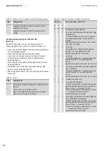
Table 24: Diagnostic status through AS-Interface
®
parameter channel
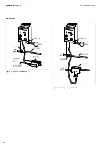
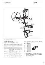
Configuring external inputs for RA-SP-HE…
(pins 3–6)
The RA-SP-HE provides two plus two external inputs for
connecting light barriers, sensors, etc. Add-on functions are:
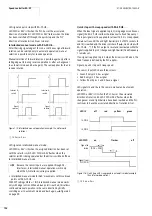
• Quick stop and interlocked manual mode with two light barriers
for one operating direction
• Quick stop with a light barrier for both directions
• Quick stop with one light barrier per direction of rotation
• Interlocked manual operation with one light barrier per
operating direction
• Quick stop and creep speed with two light barriers for each
operating direction
• Interlocked manual mode and creep speed with two light
barriers for each operating direction
• When using break contacts, inversion of the signals for internal
processing.
Table 25: Sensors
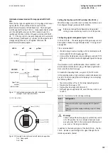
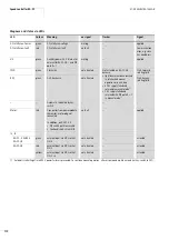
Table 26: Setting quick stop and interlocked manual mode
Pole 2
Configuration
0
Diagnostics through AS-Interface
®
parameter channel
disabled (default setting)
1
Diagnostics through AS-Interface
®
parameter channel
enabled
Pole 3
Configuration
0
Sensor signals through AS-Interface®, no add-on function
(default)
1
When using sensors with break contacts:
Signals are inverted for internal processing; the original
signals are sent through AS-Interface®.
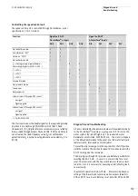
DIP pins
Add-on functions, RA-SP-HE…
4
5
6
0
0
0
No additional functions (default)
1
0
0
Quick stop and interlocked manual operation (edge-
controlled only):
I3A and I4A enabled. I3A and I4A are assigned to
forward operating direction. Reverse direction is
disabled;
Application example: vertical sorter > 360° eccentric
and > 360° rotary table
0
1
0
Quick stop:
I3A enabled. I3A is assigned to both operating
directions. I4A has no additional function;
Application example: chain discharger
0
0
1
Quick stop:
I3A and I4A enabled. I3A is assigned to operating
direction Forward, I4A to operating direction
Reverse;
Application example: vertical sorter < 360° eccentric
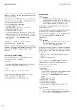
0
1
1
Quick stop and interlocked manual mode (edge- and
signal-controlled):
I3A and I4A enabled. I3A is assigned to operating
direction Forward, I4A to operating direction
Reverse;
Application example: vertical sorter < 360° eccentric
1
1
0
Invalid/error message at DI1
1
0
1
Quick stop and creep speed:
I3A/B and I4A/B enabled. I3A and B are assigned to
operating direction Forward, I4A and B to direction
Reverse. When I…B is reached, RA-SP-HE…
switches to creep speed at fixed frequency 1. When
I…A is reached, the drive switches off;
Application example: rotary table
1
1
1
Quick stop and interlocked manual mode (edge- and
signal-controlled) and creep speed:
I3A/B and I4A/B enabled. I3A and B are assigned to
operating direction Forward, I4A and B to direction
Reverse. When I…B is reached, RA-SP-HE…
switches to creep speed at fixed frequency 1. When
I…A is reached, the drive switches off;
Application example: rotary table
Содержание Rapid Link
Страница 10: ...01 08 AWB2190 1430GB 6 ...
Страница 40: ...01 08 AWB2190 1430GB 36 ...
Страница 48: ...01 08 AWB2190 1430GB 44 ...
Страница 70: ...01 08 AWB2190 1430GB 66 ...
Страница 145: ...01 08 AWB2190 1430GB Parameterization with DrivesSoft 141 Figure 134 Example acceleration time ...
Страница 146: ...01 08 AWB2190 1430GB 142 ...
Страница 162: ...01 08 AWB2190 1430GB 158 ...