

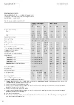

Motor starter RA-MO
(from Version 3.0)
01/08 AWB2190-1430GB
76
Description of functions
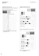
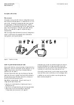
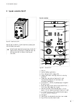
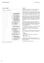
Phase reversal
Three-phase motors work with clockwise rotating fields (viewed
from the motor shaft) when phase L1 is connected to U1, L2 to V1
and L3 to W1. This default operating direction may be reversed
through gearboxes or different mounting positions. With the
reversing starter, the operating direction can be reversed with the
phase reversal switch (pole 7 of the DP switch under the front
locking screw,
a
table 14, page 81) without rewiring or
reprogramming.
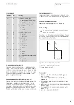
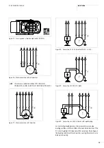
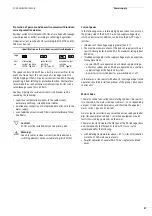
With control signal FWD (LED FWD lit) a clockwise rotating field is
output in switch position Top (default) and an anticlockwise
rotating field in switch position Bottom.
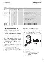
Quick stop and interlocked manual mode
Motor starter RA-MO has two external inputs, through which two
light barriers, sensors or limit switches can be connected. You can
configure these inputs as Quick Stop or Interlocked Manual
operation with DIP switches.
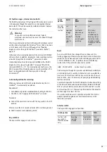
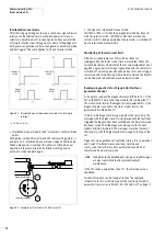
The Quick Stop function allows precision stopping of the drive.
When the limit switch is reached, the drive switched off directly
through preprocessing of the motor starter. PLC and bus cycle
times do not affect the power-off times.
Depending on yuor application, there are several ways of
configuring the Quick Stop function:
• Input I3 acts on both directions of rotation and I4 has no
additional function.
• Input I3 acts on Forward direction and I4 on Reverse direction.
• Inputs I3 and I4 act on Forward direction,
“Configuration overview (pins 5 to 8)”, page 80.
Interlocked manual mode can prevent damage to the conveyed
material and the plant in also manual operation. If you have
selected this function, limit switch I3 limits the possible forward
travel and limit switch I4 limits the possible reverse travel.
If the material reaches the limit switch in Manual mode, the drive
stops even if the selector switch remains in an actuating position.
In addition you can use this function to ajust the light barriers
before commissioning the PLC.
Figure 81: Direction of rotation
L1L2L
3
1 7
3
U V W
FWD
FWD
L1 L2 L
3
1 7
3
U V W
FWD
ON
7
ON
7
Содержание Rapid Link
Страница 10: ...01 08 AWB2190 1430GB 6 ...
Страница 40: ...01 08 AWB2190 1430GB 36 ...
Страница 48: ...01 08 AWB2190 1430GB 44 ...
Страница 70: ...01 08 AWB2190 1430GB 66 ...
Страница 145: ...01 08 AWB2190 1430GB Parameterization with DrivesSoft 141 Figure 134 Example acceleration time ...
Страница 146: ...01 08 AWB2190 1430GB 142 ...
Страница 162: ...01 08 AWB2190 1430GB 158 ...