61
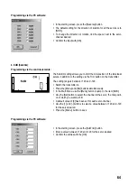
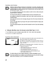
Programming via the PC software:
Install the enclosed software according to the instructions in the section „Programming the
transmitter with the PC software“. Switch on the transmitter, connect it to the PC and select the
respective COM port. To use the control elements to adopt data saved in the transmitter, import
the data with the [GetUser] button.
You can program all the Main Menu items available one after the other, without leaving the
programming mode intermittently.
The newly selected settings are not activated until they have been confirmed with [OK].
This transfers the settings to the transmitter, where they can then be called up directly on the
transmitter display.
If an invalid value is entered, an error message will appear. Correct the value as indicated in the
error message.
To leave a menu item without any change or when you do not want to adopt the changes, press
the [Cancel] button.
To leave the programming mode, disconnect the transmitter from the PC and end the program.
To make optimum use of programming via the software, for some functions you first have to
activate one or both toggle switches and/or the rotary controller on the transmitter, and allocate
the respective function to the switch/rotary controller.
This can only be done via the software.
In the default setting, rotary controller A is linked to Channel 5 of the receiver.
c) Setting the Main Menu items for winged models (Model Type 0)
1. EP (End-point adjustment)
Programming via the control elements:
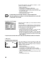
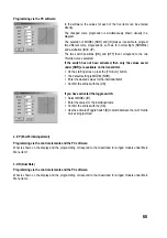
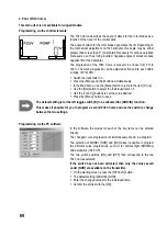
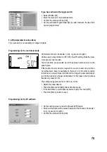
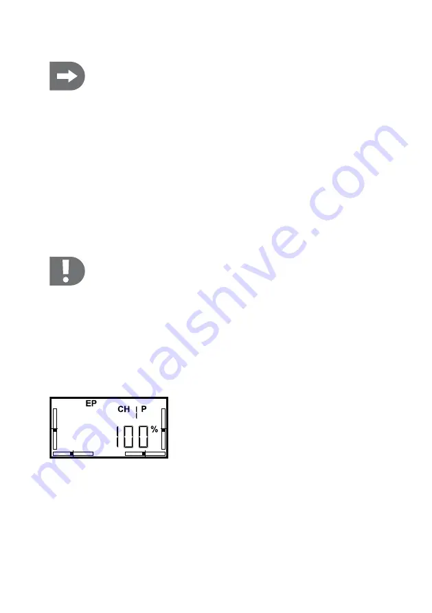
The End-Point Adjustment makes it possible to determine the maximum
deflection for each individual servo in each direction however you like.
This setting is effective on the respective servo channel and all the func-
tions mixed in for that channel as well as on the Dual Rate setting and
the trim travel.
Before you limit the servo travels, you should therefore ensure that the
factory setting of 100% is still saved for the Dual Rate.
Doing so, you can prevent (among other things) a control function from
deflecting all the way to a mechanical end stop, possibly damaging the
respective servo or the control linkage.
The control elements can be used to limit the end points of the servo
travels for Channels 1-6 between 0% and 100%.
Содержание 206501
Страница 178: ...178 ...
Страница 179: ...179 ...

