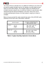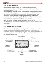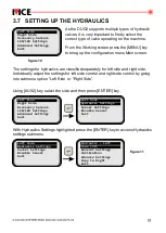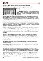
3. FIRST STEPS
3.1 BASIC SETUP
This chapter will provide you with information n connecti and setting up
i
ng
DUO2
,
. In addition a description of the symbols and displays used in the working
window will be explained.
The DUO control panel can be setup in multiple different configurations as
2
illustrated below.
+
12-24v
Battery
-
HYDRAULIC/AUX
JOYSTICK(S)
SENSOR(S)
ZERO
UP
DOWN
DOWN
UP
DUO²
v2
MAST
AUX 2
AUX 1
12-24 V DC
A
M
A
M
REF
+
-
ver
5.11
OPTIONAL
Joystick A.RS.052
or
Joystick A.RS.082
A.RS.001.NC
A.RS.080
Optional Sensors
2 x Laser Receivers
1 x Laser Receiver
1 x Sonic Tracer
1 x Laser Receiver
1 x Slope Sensor
1 x Sonic Tracer
1 x Slope Sensor
1 x GPS
1 x Slope Sensor
AU STR ALIA N M A DE
AU STR ALIA N M A DE
AU STR ALIA N M A DE
AU STR ALIA N M A DE
IB.DUO CAN
2.
CAN CABLE OPTIONS
A.R.S.111 (2.5m)
A.R.S.111 (4.5m)
A.R.S.111 (5.0m)
A.R.S.111 (10.0m)
A.R.S.106 (CURLY CORD)
1.7m un-streched
8.5m stretched
LASER RECEIVER MODELS
R.ULS Series
R.ULS.MM
R.ULS.MM.1000
UP
Optional Hydraulic Valve Connector
DOWN
LEFT
RIGHT
UP
DOWN
figure 8


