


Skylle 1550 User Manual 20181107V2
|30
9
/
31
Mount the A2 flight
control system on
youraircraft finish
connection.
Configure the
system using A2
Assistant software.
Basic flying test
FailSafe and Low-
voltage settings
Advanced functions:
IOC, Gimbal, Gear
4. AIRCRAFT PROFILES
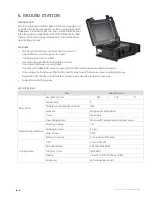
FLIGHT CONTROLLER
The A2 flight control system uses the Controller Unit at its core, which is connected with the IMU, GPS-COMPASS PRO PLUS,
LED- BT-I, PMU and ESCs to complete the system. The system can achieve the height-lock and position-lock functions by using
the IMU and the GPS, to control the aircraft.
Please carry out the following procedures to finish assembly, configuration and flight-testing:
SYMBOL INSTRUCTIONS
General Symbol
s
Forbidden
(Important)
Cautions
Tips
Reference
GPS Satellite number
Distance
TX signal good
TX signal lost
Roll to left
Roll to right
Pitch up
Pitch down
LED Symbo
l
(N)
N=1
N=2
N=3
N=4
N=6
N=20
N=
Meaning
One Blink
Two Blinks
Three Blinks
Four Blinks
Six Blinks
Twenty Blinks
Continuous
Blinks
(3) means three red blinks.
(
) LED blinks yellow and green alternatively.
(N)
N=
Meaning
Continuous Solid on
(
) means continuous blue solid on.


