background image

Eng-6

En
g

lis

h

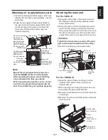
Attaching the main unit

For VL-100U

5

-E

+DQJWKHFDWFKKROHVRQWKHPDLQXQLWRQWR

WKHFDWFKHVRIWKHPRXQWLQJSODWHDVVKRZQ

EHORZ%RWKVLGHV

2) Press the main unit into the wall and secure 

it with the two screws provided. At this time, 

¿UPO\SUHVVWKHSRZHUFRUGLQWRWKHFXWRXWRQ

WKHVLGHRIWKHPDLQXQLW7KHXQLWZLOOQRWVLW

VQXJO\LIWKHFRUGLVQRWVHDWHGLQWKHFXWRXW

Caution


Tighten the two screws securely. (The joint 
gap could cause the wall to become dirty.)

3) Insert the power plug into a wall outlet.

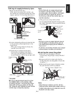
For VL-100EU

5

-E

2SHQWKHSDQHO3ODFH\RXU¿QJHUVRQWKH

FHQWHUVRIWKHVLGHVRIWKHXQLWDQGSXOO

IRUZDUGDQGXS

When opening and closing the panel, be sure 
not to stress the panel attachments.

5HPRYHWHUPLQDOEORFNFRYHU$IURPWKHPDLQ

unit prongs.

3) Remove the screw, and then remove terminal 

EORFNFRYHU%

Catch hole

Catch holes

Main unit 
mounting 
screws

Power cord

Catch

Mounting 
plate

&XWRXW

(on the 

OHIWVLGH

Main unit

Panel

Screw

Prong area 
on main unit

7HUPLQDOEORFN

cover A (plastic)

7HUPLQDO

EORFNFRYHU%

(metal)

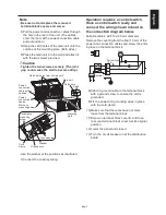
Attaching air supply/exhaust pipes

,QVHUWWKHDLUVXSSO\H[KDXVWSLSHVZKLFKDUH

attached to the pipe mounting plates, into the 
wall holes.

7DSHWKHDLUVXSSO\H[KDXVWSLSHVWLJKWO\WR

WKHZDOODVVKRZQEHORZXVLQJRIIWKHVKHOI

DOXPLQXPWDSH,IWKHVHDOLVQRWWLJKWWKH

SLSHVPD\VKLIWDQGWKHVKXWWHUPD\QRW

operate properly.)

Note


Mount the air supply/exhaust pipes A so 
that the UNDER marker is at the bottom.


After mounting the pipes, check that they 
slope downward as they go outside.


When mounting the weather covers, do not 
push the air supply/exhaust pipes into the 
wall. (The shutter may not operate properly.)

Air supply side

Air supply/
exhaust pipe

Pipe mounting 
plate

7DSHZLWK

aluminum tape 
to cover prongs 
(4 locations).

6HHIURPIURQW

Pipe mounting plate

Mount the air 
supply/exhaust 
pipes A and pipe 
mounting plates 
tightly to the wall so 

WKH\GRQRWVKLIW

Aluminum tape
Apply so that it 
does not cover 
the pipe opening.

Aluminum tape
(on both air 
supply and 
exhaust sides)

Exhaust side

81'(5PDUN

Содержание VL-100EU5-E

Страница 1: ...Mitsubishi Lossnay Ventilator MODEL VL 100U5 E pull cord Type VL 100EU5 E wall switch Type Installation Manual 1305875HF7701 ...

Страница 2: ...ttaching the main unit 6 Outdoor construction 8 KHFNV DIWHU PRXQWLQJ 9 7HVW UXQ 9 Hazards created by mishandling and their severity are indicated by the following markers Warning This applies to mishandling or misoperation of the product which could lead to a fatal or serious injury Caution This applies to mishandling or misoperation of the product which will lead to an injury or damage to your ho...

Страница 3: ...ring the unit could UHVXOW LQ HOHFWULF VKRFN UH RU LQGRRU items getting wet Be sure to shut off circuit breakers or remove the power plug from the wall outlet if the Lossnay will not be used for a long period after installation Failure to do so could result in HOHFWULF VKRFN IURP GHWHULRUDWHG LQVXODWLRQ RU UH IURP D VKRUW FLUFXLW When attaching the main unit on the wall press the main unit against...

Страница 4: ...Spread out cardboard or the like lay the vinyl sheeting used to pack the main unit on top of it and with the main unit placed upside down as shown in the drawing remove the mounting plate The shutter of the Lossnay is closed for shipment Main unit Mounting plate 6FUHZV IRU VHFXULQJ main unit Spread cardboard or a similar material 9LQ O VKHHWLQJ Ŷ 0RXQWLQJ SRVLWLRQ GLDJUDP VHHQ IURP LQVLGH 8QLW PP ...

Страница 5: ...RQ WKH ZDOO KROHV DZD IURP REVWUXFWLRQV in the wall within the ranges shown in the mounting position diagram on page 3 RRG VFUHZ IDVWHQ ORRVHO Mounting plate 5HLQIRUFHPHQW At least PP At least 83 mm At least 83 mm At least 64 mm 3 Drill the wall holes 5HPRYH WKH ORRVHO IDVWHQHG PRXQWLQJ SODWH HDYH WKH ZRRG VFUHZ ORRVHO IDVWHQHG LQ SURFHGXUH LQ SODFH ULOO WKH ZDOO KROHV RI WR PP Note Make the holes...

Страница 6: ...ply H KDXVW SLSH Air supply exhaust SLSH Air supply exhaust pipe A Air supply exhaust pipe A Caulking Caulking Catch Attach under the catches Mounting plate Plumb bob Wood screw Wood screw loosely attached screw Catch Cutting air supply exhaust pipes 0HDVXUH WKH ZDOO WKLFNQHVV I WKH ZDOO LV PRUH WKDQ PP WKLFN XVH WKH SURYLGHG DLU VXSSO H KDXVW SLSH 6HH SDJH VHFWLRQ IRU PRXQWLQJ LQVWUXFWLRQV 2 Cut ...

Страница 7: ...on the OHIW VLGH Main unit Panel Screw Prong area on main unit 7HUPLQDO EORFN cover A plastic 7HUPLQDO EORFN FRYHU metal Attaching air supply exhaust pipes QVHUW WKH DLU VXSSO H KDXVW SLSHV ZKLFK DUH attached to the pipe mounting plates into the wall holes 7DSH WKH DLU VXSSO H KDXVW SLSHV WLJKWO WR WKH ZDOO DV VKRZQ EHORZ XVLQJ RII WKH VKHOI DOXPLQXP WDSH I WKH VHDO LV QRW WLJKW WKH SLSHV PD VKLIW...

Страница 8: ...ounting plate Main unit Power connection cable pullout position Cord clamp mounting screw Ground screw Cord clamp Ground wire Operation requires a control switch Have a control switch ready and connect the wiring shown in bold on the connection diagram below 6XLWDEOH FDEOHV WR PP GLDPHWHU 5HPRYH WKH FRYHULQJ IURP WKH QDO PP RI WKH power and connection cables and screw the ends in place on the term...

Страница 9: ...ne area to ensure that the air supply and exhaust do not mix Mount the blocked parts on both the air supply and exhaust sides so that they are on the left as shown above If the weather covers shift check that the air supply exhaust pipes are cut to the correct dimensions Pushing the pipes too hard into the wall may cause the pipes to shift or prevent the shutter from operating properly Weather cov...

Страница 10: ...h as the owner or manager Checks after mounting Ŷ IWHU PRXQWLQJ LV FRPSOHWH FKHFN WKH FKHFNOLVW LWHPV EHIRUH GRLQJ D WHVW UXQ Ŷ H VXUH WR FRUUHFW DQ SUREOHPV GLVFRYHUHG DLOXUH WR GR VR ZLOO QRW RQO SUHYHQW IHDWXUHV IURP RSHUDWLQJ LW ZLOO DOVR LPSHULO RXU VDIHW Ŷ KHFNOLVW Check items 5HPHG IRU SUREOHP Checked Installation Is the main unit mounting strong enough 5HLQIRUFH LW Is the main unit attache...

Отзывы: