


Eng-7
En
g
lis
h
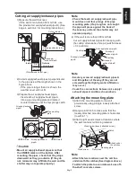
Note
Be sure not to misplace the removed
terminal block covers and screw.
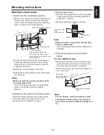
4) Pull the power and connection cables through
WKHKROHLQWKHUHDURIWKHXQLW7KHFDEOHV
enter the room at the power/connection cable
SXOORXWSRVLWLRQ
5)
+DQJWKHFDWFKKROHVRIWKHPDLQXQLWRQWRWKH
FDWFKHVRIWKHPRXQWLQJSODWH%RWKVLGHV
6) Press the main unit into the wall and attach it
with the two screws provided.
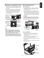
Caution
-
Tighten the two screws securely. (The joint
gap could cause the wall to become dirty.)
8VHWKHZDVKHUDWWKHSRVLWLRQVDVLOOVXWUDWHG
7) Connect the Lossnay wiring.
Washer
&DWFKKROHVRQUHDURIPDLQXQLW
Main unit
mounting screws
Power/
connection
cables
Catch
Catch hole
Mounting
plate
Main unit
Power/
connection
cable pullout
position
Cord clamp
mounting
screw
Ground screw
Cord
clamp
Ground wire
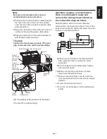
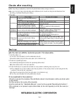
Operation requires a control switch.
Have a control switch ready and
connect the wiring shown in bold on
the connection diagram below.
6XLWDEOHFDEOHV¡WR¡PPGLDPHWHU
5HPRYHWKHFRYHULQJIURPWKH¿QDOPPRIWKH
power and connection cables and screw the ends
in place on the terminal block.
8) Attach a ground cable to the terminal block
with a ground screw to ensure the unit is
grounded.
9) Fix the power and grounding wires in place
with the cord clamp.
0DNHVXUHWKDWWKHZLUHVKDYHQRWFRPH
ORRVHIURPWKHWHUPLQDOEORFN
6FUHZRQWHUPLQDOEORFNFRYHU%DQGWKHQ
UHPRXQWWHUPLQDOEORFNFRYHU$DWLWVRULJLQDO
position.
/RZHUWKHSDQHODQGFORVHLW
7XUQWKHFLUFXLWEUHDNHURQDWWKHGLVWULEXWLRQ
board.
C
Hi
Lo
Lo
Hi
COM
M
Operating indicator
&XUUHQWIXVH
$
Motor
Isolator


