-
16
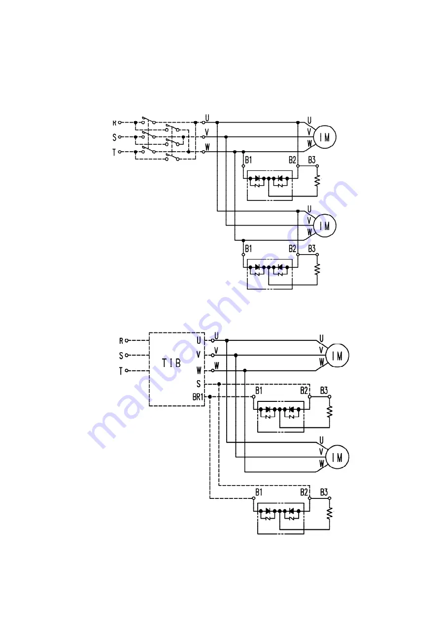
5.3 Standard wiring example 5.3.1 Magnetic contactor for drive
5.3.2 Inverter drive
3-phase power supply
Magnetic contactor
Brake coil
Страница 1: ...instruction manual to the person in charge of facilities before starting operation Be sure to have the person in charge of facilities and operators read this manual of facilities and operators read th...
Страница 2: ...the crane Install the crane only in an environment of the specified conditions Avoid rain or water that the crane is not designed for Be sure to ground the crane In addition to the grounding provide t...
Страница 3: ...for the intended work Be sure to turn off the power before leaving the operating position 4 Maintenance inspection and modification Danger Do not use any part or device of the crane beyond its service...
Страница 4: ...NSTALLATION OF MAIN BEAM 1 2 INSTALLATION OF SADDLE ASSEMBLY TO RAILS 5 3 INSTALLATION OF STOPPERS 10 4 CONSTRUCTION OF CEARED MOTOR 11 5 WIRING 15 6 TEST OPERATION 17 7 CAUTIONS 18 8 MAINTENANCE 19 9...
Страница 5: ...nd saddle as shown in Fig 5 Unit mm I BEAM 100 125 150 W 540 565 590 A 160 185 210 Width W of gusset plate should be at least 540mm Notes 1 The saddle frame is made of channel steel in compliance with...
Страница 6: ...eams stays and truss are shown in Fig 8 10 Even when crane span is short it is recommended to use reinforcement means such as stays I BEAM A W 100 60 440 125 75 455 150 100 480 Center mark Fig 7 Unit...
Страница 7: ...where stays are used span less than about 10m Examples of installation where sub truss is used span over 10m Weld after positioning 18 M16 bolt Fig 9 Weld after positioning only on one side Weld after...
Страница 8: ...shown in Fig 11 within the range of tolerance specifiedy by JIS If the clearance is large use a shim plate or spacer to eliminate the clearance 2 Center marks are stamped on saddle frame to make easy...
Страница 9: ...directly installed to the I beam listed below When I beam having dimensions other than specified below is used saddle must be reassembled as instructed below Saddle model Directly applicable I beam Ap...
Страница 10: ...pins were located at delivery from the factory as shown below SP 0 2D Type A SP 0 4D Type B A is not used 3 This procedure is completed by fastening the joining member on the saddle frame movable with...
Страница 11: ...ove the wheel 2 Grounding When the wheel is removed ground the saddle on the main beam in the assembled state and lift the crane in order to align the center of the travel rail to that of the saddle 3...
Страница 12: ...t looseness and assure powerful clamping HT nut and spring nut are used to hold side roller in position Adjustment procedure Adjustment can be made in manner other than described here so far as HT nut...
Страница 13: ...end wrench or open end wrench for M18 applied to the HT nut tighten torque 216N m to 275N m and then tighten the spring nut to prevent looseness of the HT nut 2 2 4 Caution Do not leave the saddle sto...
Страница 14: ...han cushion rubber strikes stopper frequently If cushion rubber is found deteriorated or damaged immediately replace it with a new one Stopper can be installed as exemplified below 1 TOP RUNNING type...
Страница 15: ...sembled apply grease to all tooth faces of 1st gear motor shaft 2nd gear and spur gear out of gear case Recommended grease MOLY PS GREASE 2 SUMIKO LUBRICANTS CO Model Amount of grease SP 0 2D Type SP...
Страница 16: ...0 4kW 4P ST 075D Type ST 0 75D U Type 0 75kW 4P ST 2 2D Type 2 2kW 4P 4 3 Electromagnetic brake The brake is a disk type electromagnetic brake having DC magnet and located on counter load side of moto...
Страница 17: ...alf to adjust the gap to 0 3 0 4mm If the gap is excessive however the motor shaft may not be released from the brake disk during operation 1 Adjustment of brake Remove the brake cover and turn the ad...
Страница 18: ...excessively worn brake disk is used Danger Do not use brake disk more than wear limits It could lead to the motor burnout if the motor is operated without pulling the moval core Number of brake disks...
Страница 19: ...wiring of power and power of brake to the upper stage screw as shown on the diagram to Motor conductor1 to Brake coil conductor2 lead wire lower stage upper stage lead wire to Motor to Brake coil lead...
Страница 20: ...3 Standard wiring example 5 3 1 Magnetic contactor for drive 5 3 2 Inverter drive 3 phase power supply Magnetic contactor Brake coil Brake coil Brake coil Brake coil Magnetic contactor 3 phase power s...
Страница 21: ...dition to check if the hook block goes up If the hook block goes down change power phase sequence as follows Open power contactor and interchange connection on the contactor secondary side between R p...
Страница 22: ...ock for the rated capacity Do not let anyone ride on or step on the suspended load Never use the crane to transport or lift a person Stay away from under a suspended load Do not operate the crane if a...
Страница 23: ...ny stopper deformed or removed Are all stopper mounting screwstight Are the runway rails grounded properly grounding resistance 1000 or less Are the rails in good condition wear loose joint damage cra...
Страница 24: ...ishi genuine parts only Warning Be sure to turn off the power before starting maintenance inspection or repair Only the personnel with the expert knowledge designated by the firm are allowed to mainta...
Страница 25: ...Cable There should be no external damage and deterioration Insulation in cireuit 0 2M for 200V class motor 0 4M for 400V class motor ST D SP D Wear if wheel Flange thickness Wear limit is 50 of initi...
Страница 26: ...ST 0 4D4 ST 0 4D5 L Item Description Item Description Item Description 1 Gear Cover 6 Axle 11 Wheel F 2 Buffer Rubber 7 Ball Bearing 3 Washer 8 Plate 4 Wheel L 9 Saddle Geard Motor 5 Lock Plate 10 Sa...
Страница 27: ...em Description Item Description Item Description 1 Lock Plate 6 Ball Bearing 11 Wheel F 2 Gear Cover 7 Axle 3 Buffer Rubber 8 Plate 4 Washer 9 Saddle Geard Motor 5 Wheel L 10 Saddle Flame motor is ins...
Страница 28: ...RUNNNING TYPE SADDLE ST 2 2D2 W Item Description Item Description 1 Gear Cover 6 Axle 2 Buffer Rubber 7 Lock Plate 3 Gear 8 Wheel L 4 Ball Bearing 9 Saddle Flame 5 Saddle Geard Motor 10 Wheel F P64540...
Страница 29: ...tion Item Description 1 Idle Gear 6 Key Plate 11 Axle 16 Saddle Flame Remove 2 Ball Bearing 7 Spacer 12 Plate 17 Saddle Flame Fix 3 Split Pin 8 Buffer Rubber 13 Ball Bearing 18 Wheel F 4 Idle Shaft 9...
Страница 30: ...Item Description Item Description 1 Gear Cover 6 Lock Plate 11 Plate 2 Buffer Rubber 7 Axle 12 Wheel F 3 Washer 8 Ball Bearing 13 Saddle Flame 4 Wheel L 9 Saddle Geard Motor 14 Earth Roller Assembly...
Страница 31: ...n Item Description Item Description 1 Gear Cover 6 Lock Plate 11 Plate 2 Buffer Rubber 7 Axle 12 Wheel F 3 Washer 8 Ball Bearing 13 Saddle Flame 4 Wheel L 9 Saddle Geard Motor 14 Earth Roller Assembly...
Страница 32: ...et M11 Terminal Block G02 No 2 Gear B03 Cover M03 Stator Coil M12 Cover G03 Washer B04 Stationary Core M04 Stator Core M13 Terminal box base G04 Ball Bearing B05 Brake Coil M05 Roter G05 No 3 Gear B06...
Страница 33: ...ey B02 Adjusting Screw M02 L Bracket M11 Terminal Block G02 No 2 Gear B03 Cover M03 Stator Coil M12 Cover G03 Washer B04 Stationary Core M04 Stator Core M13 Terminal Box Base G04 Ball Bearing B05 Brak...
Страница 34: ...Shaft G01 No 2 Gear B02 Adjusting Screw M02 Terminal Block M11 Stator Flame G02 Ball Bearing B03 Cover M03 Terminal Cover M12 Ball Bearing G03 No 3 Gear B04 Stationary Core M04 Terminal Box Flame G04...
Страница 35: ...ake Disk G03 Key G15 Oil immersed M03 Cover B03 Pin G04 No 3 Gear M04 Terminal Block B04 Brake Gear G05 No 4 Gear M05 Plate B05 Movable Core G06 Ball Bearing M06 Parallel Pin B06 Cover G07 Key M07 L B...
Страница 36: ...djusting Screw M02 Stator Coil M11 Cover G02 No 2 Gear B03 Cover M03 Stator Core M12 Terminal Box Bace G03 Washer B04 Stationary Core M04 Rotor G04 Ball Bearing B05 Brake Coil M05 Motor Shaft G05 No 3...
Страница 37: ...al Box Bace G02 No 2 Gear B03 Cover M03 Stator Core G03 Washer B04 Stationary Core M04 Rotor G04 Ball Bearing B05 Brake Coil M05 Motor Shaft G05 No 3 Gear B06 Movable Core M06 Stator Frame G06 Housing...
Страница 38: ...is modified altered or operated in a manner that are not admitted by regulations or by the manufacturer 2 Defects caused by the following events 1 Defects due to external factors and causes such as sm...
Страница 39: ...MITSUBISHI ELECTRIC FA INDUSTRIAL PRODUCTS CORPORATION Specifications subject to change without notice...