background image

4-86   

List of commands

4Software

4 Software
4.1 List of commands

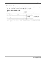
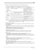
The available new functions in MELFA-BASIC Ⅴ are given in 

Table 4-1

Table 4-1 : List of MELFA-BASIC Ⅴ commands

Type

Class

Function

Input format (example)

Position and operation c

o

ntrol

Joint interpolation

Moves to the designated position with joint interpolation.

Mov P1

Linear interpolation

Moves to the designated position with linear interpolation.

Mvs P1

Circular interpolation

Moves along a designated arc (start point → passing point → start point 
(end point)) with 3-dimensional circular interpolation (360 degrees).

Mvc P1,P2,P1

Moves along a designated arc (start point → passing point → end point) with 
3-dimensional circular interpolation.

Mvr P1,P2,P3

Moves along the arc on the opposite side of a designated arc (start point →
reference point → end point) with 3-dimensional circular interpolation.

Mvr2 P1,P9,P3

Moves along a set arc (start point → end point) with 3-dimensional circular 
interpolation.

Mvr3 P1,P9,P3

Speed designation

Designates the speed for various interpolation operations with a percentage 
(0.1% unit).

Ovrd 100

Designate the speed for joint interpolation operation with a percentage 
(0.1% unit).

JOvrd 100

Designates the speed for linear and circular interpolation with a numerical 
value (mm/s unit).

Spd 123.5

Designates the acceleration/deceleration time as a percentage in respect to 
the predetermined maximum acceleration/deceleration. (1% unit)

Accel 50,80

Operation

Adds a process unconditionally to the operation.

Wth

Adds a process conditionally to the operation.

Wthif

Designates smooth operation.

Cnt 1,100,200

Designates the positioning completion conditions with a No. of pulses.

Fine 200

Turns the servo power ON/OFF for all axes.

Servo OFF

Limits the operation of each axis so that the designated torque is not 
exceeded.

Torq 4,10

Position control

Designates the base conversion data.

Base P1

Designates the tool conversion data.

Tool P1

Pallet

Defines the pallet.

Def Plt 1,P1,P2,P3,P4,5,3,1

Operates the pallet grid point position.

Plt 1,M1

Progr

am control

Branching

Branches unconditionally to the designated place.

GoTo 120

Branches according to the designated conditions.

If M1=1 Then GoTo 100 
Else GoTo 20
End If

Repeats until the designated end conditions are satisfied.

For M1=1 TO 10

Next M1

Repeats while the designated conditions are satisfied.

While M1<10

Wend

Branches corresponding to the designated expression value.

On M1 GOTO 100,200,300

Executes program block corresponding to the designated expression value..

Select 
Case 1

Break
Case 2

Break
End Select

Moves the program process to the next line.

Skip

Impact detection

Set to enable/disable the impact detection.

ColChk ON/OFF

Set the detection level of the impact detection.

ColLvl 100,80,,,,,,

Содержание RV-12SD Series

Страница 1: ...Mitsubishi Industrial Robot RV 12SD Series Standard Specifications Manual CR3D 701M CR3D 701 Controller BFP A8656...

Страница 2: ......

Страница 3: ...on the start switch etc This also applies to maintenance work with the power source turned ON Indication of teaching work in progress Provide a fence or enclosure during operation to prevent contact...

Страница 4: ...this could lead to malfunctioning by noise or to electric shock accidents Indicate the operation state during robot operation Failure to indicate the state could lead to operators approaching the rob...

Страница 5: ...interfere with the peripheral device by drop or move by inertia of the arm Do not turn off the main power to the robot controller while rewriting the internal information of the robot controller such...

Страница 6: ...Revision history Date of print Specifications No Details of revisions 2008 05 9 BFP A8656 First print...

Страница 7: ...rd specifications and use our robots Note that in this specification document the specifications related to the robot arm is described 2 Robot arm on page 3 the specifications related to the controlle...

Страница 8: ...of the Robot 2 12 2 2 5 Protection specifications and working environment 2 13 1 Types of protection specifications 2 13 2 About the use with the bad environment 2 14 2 2 6 Clean specifications 2 15 1...

Страница 9: ...0 11 Additional axis interface 3 92 12 Extension memory cassette 3 94 13 Personal computer support software Personal computer support software mini 3 96 14 Instruction Manual bound edition 3 98 3 9 Ma...

Страница 10: ...ual 7 Guarantee card 1 1 2 Shipping special specifications Part of the standard structural equipment is changed at the time of factory shipment Consequently kindly con firm the delivery date To make c...

Страница 11: ...d the controller Table 1 1 Combination of the robot arm and the controller 1 3 Combination of the robot arm and the controllerIndirect export If you intend to export robots bought from us be sure to c...

Страница 12: ...01 3 set 1S VD03 01 4 set 1S VD04 01 Hand curl tube 4 set 8pc 1N ST0608C Stopper for changing the operating range of the J1 axis Stopper part 1S DH 01 This must be installed by the customer Caution S...

Страница 13: ...ows2000 XP Vista Instruction Manual bound edition 5S DC00 PE01 Controller CR3D 701M IP54 CR3D 701 Caster type controller CC Link interface 2D TZ576 Extension memory cassette 2D TZ454 Parallel I O inte...

Страница 14: ...position deadman switch R32TB 15 Cable length 15m R56TB Cable length 7m R56TB 15 Cable length 15m Pneumatic hand interface 2A RZ365 DO 8 point Sink type It is necessary when the hand output signal of...

Страница 15: ...uld lead to malfunc tioning USB cable USB A type USB B type USB2 30 ELECOM CO LTD AU230 BUFFALO KOKUYO SUPPLY INC USB cable USB A type USB mini B type KU AMB530 SANWA SUPPLY INC USB M53 ELECOM CO LTD...

Страница 16: ...Rating 10 Pose repeatability Note3 Note3 The pose repeatability details are given in Page 6 2 2 1 Pose repeatability mm 0 05 Ambient temperature 0 to 40 mass kg Approx 93 Approx 98 Allowable moment l...

Страница 17: ...urned OFF or a stop operation is performed halfway 4 Temperature factors 1 When the operating environment temperature changes 2 When accuracy is required before and after a warm up operation 5 Factors...

Страница 18: ...ithin the allowable range mentioned previously an overload or generate an overcurrnt alarm could occur In such cases it will be necessary to change the time setting for acceleration decel eration the...

Страница 19: ...Size Hand Conditions Set up the capacity and size of the hand with the HNDDAT parameter optimum acceleration deceleration setting parameter and set up the capacity and size of the work with the WRKDA...

Страница 20: ...one minute per 1m2 of test device surface area for a total of three minutes 2 About the use with the bad environment This robot has protection methods that conform to IEC sIP54 for J1 to J3 axis and I...

Страница 21: ...91 6 2 Working environment 1 In surroundings that generate inflammable gases or corrosive gasses 2 Atmosphere used excluding cutting oil shown in Table 2 3 3 Environment where the robot is exposed to...

Страница 22: ...he cus tomer Install the vacuum generating valve downstream of the downflow or install a filter in the exhaust air sec tion so that the exhaust air from the vacuum generating valve does not affect cle...

Страница 23: ...t Robot arm 2 3 Names of each part of the robot Fig 2 2 Names of each part of the robot J5 axis J6 axis Fore arm Mechanical interface Hand installation flange surface Upper arm J1 axis J2 axis J3 axis...

Страница 24: ...0 150 155 100 125 4 14 installation hole 2 6 holes prepared holes for 8 positioning pins View D bottom view drawing Detail of installation dimension Installation 6 3a Installation 6 3a 530 97 120 150...

Страница 25: ...eg J1 75deg and the angle of axis J2 is 25deg J2 2deg then operating range is limited to J2 J3 2 258deg If the angle of axis J1 is 75deg J1 75 deg and the angle of axis J2 is 80deg J2 25deg then opera...

Страница 26: ...150 155 100 125 2 6 holes prepared holes for 8 positioning pins View D bottom view drawing Detail of installation dimension Installation 6 3a Installation 6 3a 215 161 164 230 50 130 88 89 93 89 R 3 0...

Страница 27: ...85 97 670 150 690 470 P 716 322 1 0 0 R 6 7 5 4 0 R307 70 130 R 4 6 7R 5 6 0 R1235 R 5 6 0 R 6 7 5 200 or more R673 Flange downward limit line dotted line P point path Rear surface area wide angle nar...

Страница 28: ...SPEAR WIRE INLET Primary piping pneumatic hose Hand input signal cable Hand output signal cable Secondary piping pneumatic hose 6 customer prepared Connector and pneumatic coupling No Name Qty Robot...

Страница 29: ...1 When the controller uses the optional pneumatic hand interface 2A RZ365 RZ375 the hand output signal works as the pneumatic hand cable 2 The hand output primary cable extends from the connector PCB...

Страница 30: ...ached to the solenoid set Hand input cable option 6 quick coupling 1 to 8 Hand signal input connection connector Hand signal output connector GR1 connector AIR IN RETURN A1 A2 A3 B1 B2 B3 24V Reserved...

Страница 31: ...urrent 8VDC or more 2mA or more OFF voltage OFF current 4VDC or less 1mA or less Input resistance Approx 3 3k Response time OFF ON 10ms or less DC24V ON OFF 10ms or less DC24V Item Specification Inter...

Страница 32: ...pressure switch to the source of the air as shown in Fig 2 8 and use the circuit described so that the robot stops when pressure drops Use a hand with a spring pressure clamp or a mechanical lock type...

Страница 33: ...r needs customer installation is required for the options Options come in two types set options and single options 1 Set options A combination of single options and parts that together from a set for...

Страница 34: ...be installed on clean type but its cleanliness is not under warranty Part name Type Qty Remarks Fixed Flexed Fixed Set of signal and power cables 1S CBL 02 1 set 5m 10m or 15m eachNote1 Note1 The numb...

Страница 35: ...g 2 9 Fixing the flexible cable Item Motor signal cable 1S LCBL S 01 Motor power cable 1S LCBL P 01 Ground cable BU284D663 No of cores AWG 24 0 2mm2 4P AWG 24 0 2mm2 7P AWG 18 0 75mm2 AWG 16 1 25mm2 4...

Страница 36: ...imit by the mechanical stopper is positioned 1degrees outward from that angle so take care when designing the layout 2 The changeable angle can be set independently on the side and side 3 The operatin...

Страница 37: ...2 17 Solenoid specifications Part name Type Q ty Remark One set Two sets Three sets Four sets Solenoid valve set 1 set 1S VD01 01 1S VD01E 01 1 pc M4x8 four screws installation screws 1S VD01 01 VD02...

Страница 38: ...4 4 M4 8 SOL1A SOL1B SOL2A SOL2B White A3 GR1 A4 A1 A2 B3 B4 B1 B2 GR1 GR2 24V COM Reserve Reserve Reserve GR3 GR4 Black Red Black Red Black Red Black Red SOL3A SOL3B SOL4A SOL4B White A3 GR2 A4 A1 A...

Страница 39: ...le 2 18 Configuration equipment Specifications Table 2 19 Specifications Fig 2 11 Outside dimensional drawing and pin assignment Caution This option can be installed on clean type but its cleanliness...

Страница 40: ...tions Fig 2 12 Outline dimensional drawing and pin assignment Part name Type Qty Remarks Hand output cable 1S GR35S 01 1 cable For four sets Item Specifications Remarks Size x Cable core AWG 24 0 2mm2...

Страница 41: ...talled on clean type but its cleanliness is not under warranty Table 2 23 Specifications Fig 2 13 Outline dimensional drawing Caution This option can be installed on clean type but its cleanliness is...

Страница 42: ...ard parts Thus confirm the part name robot arm and controller serial No and purchase the parts from the dealer Table 2 24 Consumable part list No Part name Type Note1 Note1 Confirm the robot arm seria...

Страница 43: ...umatic hand interface Option slot slot 3 Additional axis interface Channel 1 SSCNET Power source Input voltage range V 3 phase AC180 to 253 Note3 Note3 Please use the controller with an input power su...

Страница 44: ...rd IP54 Closed type is adopted for the controller The IEC IP symbols refer only to the degree of protection between the solid and the fluids and don t indicated that any special protection has been co...

Страница 45: ...p switch This stops the robot in an emergency state The servo turns OFF CHNGDISP button This changes the details displayed on the display panel in the order of Override Pro gram No Line No END button...

Страница 46: ...s for which the operation mode must be at the external device or controller are not possible UP DOWN button This scrolls up or down the details displayed on the STATUS NUMBER display panel Interface c...

Страница 47: ...he pneumatic hand interface optional Option slot SLOT1 SLOT2 SLOT3 Install the interface optional Extension parallel input output unit connection connector RIO Connect the extension parallel input out...

Страница 48: ...ide dimensions 3 4 Outside dimensions of controller CR3D 700 550 65 615 45 35 420 15 15 380 3 2 75 550 625 450 35 40 5 79 5 320 440 134 55 340 55 380 60 95 288 SVO OFF STOP END SVO ON MODE START RESET...

Страница 49: ...700M Supplement 3 6 Outside dimensions of controller CR3D 700 Supplement Right side drawing Back drawing Exhaust Suction Exhaust 380 60 140 75 625 CN2 CN1 122 123 70 FAN FAN 7 000 CR3D 700M Right sid...

Страница 50: ...ide Approx Back 500 Note Front 500 Approx View from upside Maintenance area View from upside Maintenance area Approx Back 500 Note Front 500 Approx 300 Approx Side Side Approx 200 Controller upside No...

Страница 51: ...output signal lead in port with sponge 3 Left surface cable outlet 4 Right surface input output signal lead in port no sponge with cabl fixing plate Use 1 to lead in the input power cable Use 2 or 4 t...

Страница 52: ...3 Hand input output These are inputs and outputs related to the hand that the customer can program Table 3 2 Emergency stop Door switch input The wiring for the safe security of the emergency stop etc...

Страница 53: ...the STOP parameter change of the signal number is possible Notes specification is the same as the STOP parameter Wait output signal Outputs that the slot is temporarily stopped SLOTINIT Program reset...

Страница 54: ...e jog mode Jog mode output 2 bit Outputs the current jog mode JOG Jog feed side for 8 axes Requests the side jog operation None JOG Jog feed side for 8 axes Requests the side jog operation None HNDCNT...

Страница 55: ...emergency line type wire both contacts to the two terminal blocks on the controller If both contacts are wired to only one of the terminal blocks errors cannot be cancelled using the door switch The c...

Страница 56: ...3 43 Fig 3 9 Emergency stop cable connection CR3D 700 R700SFT EMGIN EMGOUT 30cm CR3D 700 700M Pin allotment of EMGIN and the EMGOUT connector is shown in Page 44 Fig 3 10 External emergency stop conne...

Страница 57: ...A 6A 5A 4A 3A 2A 1A 11B 10B 9B 8B 7B 6B 5B 4B 3B 2B 1B EMGOUT pin arrangement EMGOUT2 EMGOUT1 6A 5A 4A 3A 2A 1A 6B 5B 4B 3B 2B 1B Type 1 1871940 6 Minus driver plug AWG 24 18 0 2 0 75mm2 Electric wire...

Страница 58: ...The skip is the input signal to stop the robot Wire 1A 1B of the special stop connector SKIP shown in Page 46 Fig 3 11 Connection of the special stop input Table 3 5 Special stop input electric specif...

Страница 59: ...B 2B 3B 4B SKIP AWG 24 18 Special stop connector Minus driver plug area Electric wire plug area AWG 24 18 The connector connection method The electric wire skins covering 7mm In the condition that the...

Страница 60: ...his function according to the robot status are shown below During automatic operation When the door is opened the servo turns OFF and the robot stops An error occurs The process of the restoration Clo...

Страница 61: ...inside the controller and Fig 3 13 shows a connection exam ple configuration example The magnet contactor control connector for additional axes AXMC1 is designed to accommodate circuit connection wit...

Страница 62: ...connection CR3 700 700M EMGOUT OPT2 R700CPU SSCNET cable SSCNET cable Servo amplifier Servo amplifier OPT connector CN1A connector CN1B connector CN1A connector Cap CN1B connector It cannot communica...

Страница 63: ...axis interface Instruction Manual for details on the additional axis function Note1 you use the addition axis function as a user mechanism who became independent of the robot arm please do not connect...

Страница 64: ...700SFT EMGOUT connector EMGOUT2 EMGOUT1 6A 5A 4A 3A 2A 1A 6B 5B 4B 3B 2B 1B Type 1 1871940 6 Minus driver plug area AWG 24 18 0 2 0 75mm2 Electric wire plug area Internal circuit EMGOUT1 EMGOUT2 Custm...

Страница 65: ...3 52 Magnet contactor control connector output AXMC for addition axes 3 Controller...

Страница 66: ...r needs User installation is required for the options Options come in two types set options and single options 1 Set options A combination of single options and parts that together form a set for serv...

Страница 67: ...ition deadman switch has three statuses The following modes are entered according to the switch state Not pressed The robot does not operate Pressed lightly The robot can be operated and teaching is p...

Страница 68: ...teaching pendant Installation method The teaching pendant is connected to the T B connector on the front of the controller Enable Disable switch Emergency stop Enable switch Operetion key Body Cable...

Страница 69: ...ecelerates the robot to a stop 9 OVRD OVRD key Change moving speed Speed goes up by OVRD key Speed goes down by OVRD key 10 JOG operation key Move the robot according to jog mode And input the numeric...

Страница 70: ...0 Specifications Part name Type Qty Remarks Pneumatic hand interface 2A RZ365 1pc Output 8 points expansion Item Specification Internal circuit Type Transistor output Sink type GRn GR1 GR8 No of outpu...

Страница 71: ...2D TZ315 securely Refer to separate Instruction Manual Controller setup basic operation and maintenance for details on the installing method Fig 3 18 Installation of the pneumatic hand interface CR3D...

Страница 72: ...ation number 0 to 2 Configuration Table 3 11 Configuration device 1 The CR3D 700 series controller can connect this three interfaces Table 3 12 Electrical specifications of input circuits Part name Ty...

Страница 73: ...station number 1 32 to 63 SLOT3 station number 2 64 to 95 If it uses together with parallel input and output unit 2 A RZ361 2 A RZ371 please do not overlap with the station number of the parallel inp...

Страница 74: ...3 Controller Parallel I O interface 3 61 Fig 3 19 Parallel I O interface installation position CR3D 700 700M SLOT1 SLOT2 SLOT3 R700CPU CR3D 700 700M unit...

Страница 75: ...SLOT1 and signal number allocation are shown in Table 3 15 and Table 3 16 If it installs in other slots please interpret and utilize Slot number Station number Range of the general purpose input and o...

Страница 76: ...purpose output 12 9C Yellow Red b General purpose input 11 9D Yellow Black b General purpose output 11 10C Pink Red b General purpose input 10 10D Pink Black b General purpose output 10 11C Orange Red...

Страница 77: ...tput 28 9A Yellow Red b General purpose input 27 9B Yellow Black b General purpose output 27 10A Pink Red b General purpose input 26 10B Pink Black b General purpose output 26 11A Orange Red c General...

Страница 78: ...The input output circuit external power supply 24 VDC must be prepared by the customer 60mA 24 12V Output Fuse 0V COM AX41C Mitsubishi programmable controller AY51C Mitsubishi programmable controller...

Страница 79: ...r 1 are 1C 2C 20C 1D 2D 20D connector 2 are 1A 2A 20A 1B 2B 20B Part name Type Qty Remarks External I O cable 2D CBL 1 pc 5m or 15m Items Specifications Number of cables x cable size AWG 28 x 20P 40 p...

Страница 80: ...ector pin numbers and cable colors when making the connections Fig 3 21 Connections and outside dimensions Eg Pin number color indication Orange Red Type of dot mark see figure below Color of dot mark...

Страница 81: ...cally fixed by the position of the option slot which installed the parallel I O interface in 0 2 Configuration Table 3 21 Configuration device Specifications 1 The parallel I O interface 2D TZ368 of a...

Страница 82: ...ss Input resistance Approx 3 3k Response time OFF ON 10ms or less 24VDC ON OFF 10ms or less 24VDC Common method 8 points per common External cable connection method Connector Item Specification Intern...

Страница 83: ...tor Pin No RIO1 2 100 TXRXH TXRXL SG GND List of parts and manufacturer Type Connector type Contact type Resistant Manufacturer NETcable 1 1 178288 3 2 175218 3 6 AMP DCcable 2 2 178288 3 1 175218 3 3...

Страница 84: ...unit CR3D 700 700M CR3D 700 700M R700CPU RIO 60 54 6 Radiation wiring space 150 6 156 2 screw 6 168 Heat radiation space 128 175 100 Wiring space 40 2A RZ361 Installation dimensions of 2A RZ361 6 down...

Страница 85: ...ation No setting 1 6 NETcable 1 cable Note RIO2 connector RIO2 connector RIO1 connector R TM terminator Station No setting 7 I O unit the bottom Connecta layout DCIN connector Connect the NET cable 1...

Страница 86: ...15 Output 0 to 15 Input 16 to 31 Output 16 to 31 2nd set 1 Input 32 to 47 Output 32 to 47 Input 48 to 63 Output 48 to 63 3rd set 2 Input 64 to 79 Output 64 to 79 Input 80 to 95 Output 80 to 95 4th set...

Страница 87: ...47 Gray Blue E General purpose input 15 23 White Red E Reserved 48 White Blue E Reserved 24 Yellow Red E Reserved 49 Yellow Blue E Reserved 25 Pink Red E Reserved 50 Pink Blue E Reserved Pin No Line...

Страница 88: ...s External I O cable 2A CBL 1pc 5m or 15m Items Specifications Number of cables x cable size 50 pairs x AWG 28 Total length 5m or 15m Pin no Cable colors Pin no Cable colors Pin no Cable colors Pin no...

Страница 89: ...eath Type of dot mark A type B type C type D type E type F type G type H type I type J type Dot pattern Receptacle type PCB side 57AE 40500 21D D8 Plug type cable side 57YE 30500 2 D8 DDK Maker DDK 26...

Страница 90: ...Personal computer cables for the PC AT compatible model is available Configuration Table 3 30 Configuration device Specifications Fig 3 27 Personal computer cabe connection Part name Type Qty Remarks...

Страница 91: ...me Type Qty Remarks CC Link interface 2D TZ576 1 Ferrite core E04SR301334 2 Be sure to install this for noise countermeasure Part name Type Qty Remarks Master station QJ61BT11 Q series 1 FX series pro...

Страница 92: ...cyclic setup 1 2 4 8 Maximum link point Remote I O RX RY Each 896 points The two last cannot be used Remote register RWr RWw Each 128 register 16 bits register Extended cyclic setup 1 fold setup 2 fol...

Страница 93: ...ard can be set by a rotary switch or DIP switch No separate space is required to mount the CC Link interface card as it is embedded in the robot controller can only be mounted into slot 2 Easy wiring...

Страница 94: ...Z454 1 Items Specifications Remarks External dimensions Approx 94 W X65 D X15 H mm Excluding the connection connector Mass Approx 0 2 kg Connection method Connection using a special connector Memory s...

Страница 95: ...check and step execution are especially sufficient and are extremely useful when editing or debugging the program With the simulation function support the program can be debugged and the tact checked...

Страница 96: ...ol list copy movement delete content compari son name change protect Debugging func tions Direct editing of program in controller Confirmation of robot program operation step execution direct exe cuti...

Страница 97: ...andling the robot Standard Specifications BFP A8599 Specification of the robot arm and controller Robot Arm Setup Maintenance BFP A8600 Installation method of the robot arm jog operation and maintenan...

Страница 98: ...d controller serial No and purchase the parts from your dealer Table 3 39 Contloller consumable parts list No Part name Type Note1 Note1 Confirm the robot arm serial No and contact the dealer or servi...

Страница 99: ...Spd 123 5 Designates the acceleration deceleration time as a percentage in respect to the predetermined maximum acceleration deceleration 1 unit Accel 50 80 Operation Adds a process unconditionally t...

Страница 100: ...nated hand HClose 1 Input output Assignment Defines the input output variables Def IO PORT1 BIT 0 Input Retrieves the general purpose input signal M1 M_IN 1 Output Calls out the general purpose output...

Страница 101: ...lid 1 1 0 User defined area An area cube defined with two XYZ coordinate points can be designated and that area set as the outside operation range Furthermore a signal can be output when the axis ente...

Страница 102: ...232 Set the character length CPRTY232 Set the parity CSTOP232 Set the stop bit CTERM232 Set the end code Slot table SLT1 SLT32 Make settings program name operation type order of priority etc for each...

Страница 103: ...Precautions for safety and technology when incorporating the robot are also explained Explains the procedures required to operate the robot arm unpacking transportation installation confirmation of op...

Страница 104: ...5Instruction Manual The details of each instruction manuals 5 91...

Страница 105: ...d the error exceeds the specified amount The drive circuit is shut off The robot stops and an alarm displays 5 AC power voltage drop diagnosis function Activates when the AC power voltage drops below...

Страница 106: ...ing Train the operators about the operations maintenance and safety required for the robot work Only trained and registered operators must operate the robot Participation in the Special training for i...

Страница 107: ...ely stop the robot operation when trouble occurs 7 The teaching operator must have completed special training regarding safety Training regarding industrial robots and work methods etc 8 Create signal...

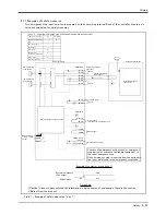
Страница 108: ...p If the emergency stop is inputted from the periphery the robot will also be in the emergency stop state Peripheral equipment Example of customer wiring case 1 Time chart System emergency stop output...

Страница 109: ...stop circuit Internal emergency stop circuit Error output Include S W emergency stop Mode output Enebling device Door switch input External emergency stop input Door switch input Error output Include...

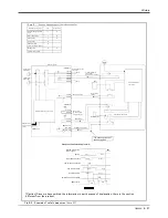
Страница 110: ...t Short Short system emergency stop output Constitute by customer Internal emergency stop circuit Door Door switch output Enabling device input Mode output Error output Include S W emergency stop Door...

Страница 111: ...e by customer Peripheral equipment With the compulsive guide Monitor Internal emergency stop circuit Door switch input Short Error output Mode output Short Enebling device input Additional axis contac...

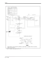
Страница 112: ...GIN1 2 Robot servo RA Contact for servo amplifier in general servos in general 5A 5B 6A 6B ON ON RA RA RA RA RA RA RA Robot controller External emergency stop input Short Short system emergency stop o...

Страница 113: ...th so refer to the following and install Switch contact Prepare a 2 contact type Switch contact capacity Use a contact that operates with a switch contact capacity of approx 1mA to 100mA 24V Cable len...

Страница 114: ...rror may occur 2 Noise Where a surge voltage exceeding 1000V 1 s may be applied on the primary voltage Near large inverters high output frequency oscillator large contactors and welding machines Stati...

Страница 115: ...eed the surface of the robot arm gets very hot It would not result in burns however it may cause secondary accidents if touched carelessly 11 Do not shut down the input power supply to stop the robot...

Страница 116: ...t provided 7m 15m Pneumatic hand interface 2A RZ365 Not provided Provided Parallel I O interface 2D TZ368 Not provided 1pc 2pc 3pc External I O cable 2D CBL 2D TZ368 Not provided 5m pc 15m 1 pc Parall...

Страница 117: ......

Страница 118: ...in Japan on recycled paper Specifications are subject to change without notice HEAD OFFICE TOKYO BUILDING 2 7 3 MARUNOUCHI CHIYODA KU TOKYO 100 8310 JAPAN NAGOYA WORKS 5 1 14 YADA MINAMI HIGASHI KU N...
Отзывы: