

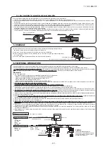


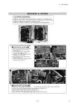
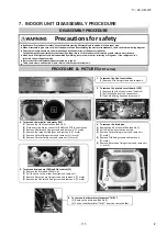


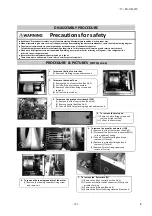

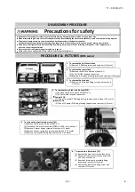


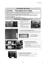

9. To remove the compressor (CM)
(1) Remove the service panel.(See No.1)
(2) Remove the insulation which covers compressor. (Strings (a)
(c) should be loosen.)
(3) Remove the terminal cover fixing bolt and remove it, and disconnect the power wiring.
(4) Remove welded part of compressor by welding. (
mark)
(5) Remove 3 compressor fixing nuts(
mark) using spanner or adjustable wrench.
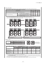
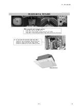
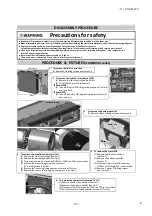
10. To remove the printed circuit board (PCB)
Control box service top side type
(1) Remove the service panel and top panel.
(2) Take off 6 hooks of lid and remove it.
(
mark, Pic.
)
(3) Pull off all the inserted connectors of
control PCB.(
mark, Pic.
)
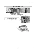
(4) Remove 4 cotrol PCB fixing screws and
remove it.(
mark, Pic.
)
(5) Pull off all the inserted connectors of
inverter PCB.(Pic.
)
(6) Remove 4 inverter PCB fixing screws and
remove it.(
mark, Pic.
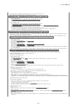
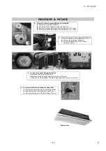
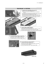
11. To remove the printed circuit board (PCB)
Control box service front side type
(1) Remove the service panel and top panel.
(2) Pull off all the inserted connectors of control PCB.(Pic.
)
(3) Take off 6 control PCB fixing locking supports and remove it.(
mark, Pic.
)
(4) Remove 5 plate fixing screws and open it.(
mark, Pic.
)
(5) Pull off all the inserted connectors of inverter PCB.(Pic.
)
(6) Take off 9 inverter PCB fixing locking supports and remove it.(
mark, Pic.
)
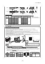
PROCEDURE & PICTURES
Control PCB
Inverter PCB
Control PCB fixing
(a)
(b
(c)
Terminal cover
Front side
Top side
Lid of control box
Control PCB
Inverter PCB
Inverter PCB
'17 • KX-SM-272
–
134
–
#
Содержание 140KXZEN1
Страница 153: ... 17 KX SM 272 151 ...
Страница 154: ... 17 KX SM 272 152 ...
Страница 155: ... 17 KX SM 272 153 ...
Страница 156: ... 17 KX SM 272 154 ...
Страница 165: ... 163 MEMO 17 KX SM 272 ...


