


–
128
–
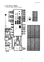
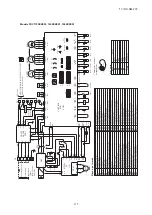
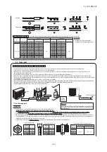
Signal line
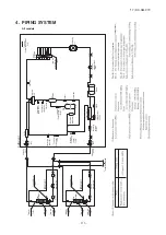
Refrigerant pipe
Outdoor unit [01]
Outdoor unit [02]
Indoor unit
Indoor unit
Indoor unit
Indoor unit
Indoor unit
Indoor unit
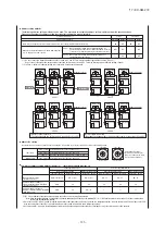
Address change (available only with new SL)
・
Within a refrigerant system, indoor units are assigned addresses in the order they are recognized by the outdoor unit. Therefore, they are not necessarily assigned
addresses in order from the nearest to the outdoor unit first as depicted in drawings above.
・
Make sure that power has been turned on to all indoor units.
・
When addresses are set, you can have the registered indoor unit address No.’s and the outdoor unit address No. displayed on the remote control unit by pressing its
inspection switch.
・
Automatic address setting can be used for an installation in which prulal indoor units are controlled from one remote control unit.
・
Once they are registered, addresses are stored in microcomputers, even if power is turned off.
・
If you want to change an address after automatic address setting, you can change it from the remote control unit with its “Address change” function or by means of
manual setting. Set a unique address by avoiding the address assigned to other indoor unit on the network when the address is changed.
・
Do not turn on power to central control equipment until automatic address setting is completed.
・
When addresses are set, be sure to perform a test run and ensure that you can operate all indoor and outdoor units normally. Also check the addresses assigned to the
indoor units.
②
OFF
①
OFF
②
indoor000/outdoor 49
(
factory setting
)
①
01,02(Ex
)
③
Disconnect(each outdoor unit)
STEP1
STEP2
STEP3
STEP4
Indoor unit
(
00
)
+01
Indoor unit
(
01
)
+01
Indoor unit
(
02
)
+01
Indoor unit
(
00
)
+04
Indoor unit
(
01
)
+04
Indoor unit
(
02
)
+04
Indoor unit
01
Indoor unit
02
Indoor unit
03
Indoor unit
02
Indoor unit
03
Indoor unit
04
Indoor unit
05
Indoor unit
06
Indoor unit
04
Indoor unit
05
Indoor unit
06
[
STEP1
]
[
STEP2
]
[
STEP3
]
[
STEP4
]
Outdoor unit [01]
Start [01]
Number [03]
Start [04]
Number [03]
Outdoor unit [02]
Outdoor unit [01]
Outdoor unit [02]
Outdoor unit [01]
Outdoor unit [02]
ー
ー
ー
ー
⑨
Connect(each outdoor unit)
ー
ー
⑩
Set in P34 on the 7-segment display
panel of any outdoor unit.
⑪「
End
」
ー
ー
ー
ー
ー
ー
ー
ー
⑧
“AUE”(blink), or “A
○○
” in error events.
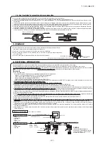
Indoor unit power source
Outdoor unit power source
Indoor unit
(indoor/outdoor No.switch)
Outdoor unit (outdoor No.switch)
Network connectors
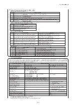
Start automatic address setting
Set starting address
Set the number of indoor unit
Polarity setting
7-segment display
Indoor unit
01
Indoor No.switch
000
000
Outdoor No.switch
49
49
Indoor unit address setting
Outdoor unit address setting
Outdoor No.switch
49
00
-
31
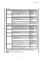
“Address change” is used,
when you want to change an indoor unit address assigned with the “Automatic address setting” function from a remote control unit
.
Accordingly, the conditions that permit an address change from a remote control unit are as follows.
If “CHANGE ADD.
▼
” is selected with some addresses falling outside these conditions, the following indication will appear for 3 seconds
on the remote control ”INVALID OPER” .
Automatic address setting for multiple refrigerant systems installation
Automatic address setting for single refrigerant system installation
④
ON
④
ON
Polarity
setting
⑦
outdoor 01:
「
03
」
(Ex)
outdoor 02:
「
03
」
(Ex)
⑥
outdoor 01:
「
01
」
(Ex)
outdoor 02:
「
04
」
(Ex)
⑤
Select “Automatic address start”
on each outdoor unit.
⑦[
AUX
]
(Blink
)
ー
ー
ー
ー
'17 • KX-SM-272
Содержание 140KXZEN1
Страница 153: ... 17 KX SM 272 151 ...
Страница 154: ... 17 KX SM 272 152 ...
Страница 155: ... 17 KX SM 272 153 ...
Страница 156: ... 17 KX SM 272 154 ...
Страница 165: ... 163 MEMO 17 KX SM 272 ...


