5 WIRING
5.1 Wiring Precautions
23
5
5
WIRING
This chapter describes the wiring of a temperature input module.
5.1
Wiring Precautions
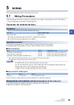
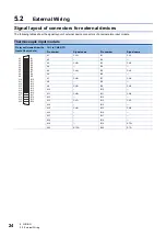
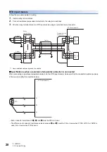
Check the signal layout and then correctly wire a temperature input module. For the signal layout, refer to the following.
Page 24 Signal layout of connectors for external devices
Connector for external devices
Precautions
• Tighten the connector screws within the specified torque range.
• Use copper wire with a temperature rating of 75
or higher for the connector.
• Use UL listed connectors if necessary for UL compliance.
Applicable connectors
Connectors for external devices to be used for a temperature input module are sold separately.
The following tables list the applicable connectors, and the reference product of a crimping tool.
■
40-pin connectors
*1 Use a cable with a sheath outside diameter of 1.3mm or less when 40 cables are connected.
Select appropriate cables according to the current value used.
• The A6CON3 (IDC type connector (straight type)) cannot be used.
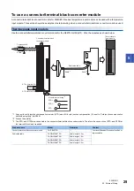
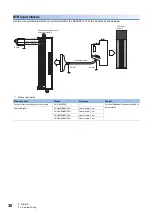
• A connector/terminal block converter module for MELSEC-Q series temperature input module and the
dedicated cable can be used. For details, refer to the following.
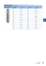
Page 29 To use a connector/terminal block converter module
■
40-pin connector crimping tool
For how to wire the connector and how to use the crimping tool, contact the manufacturer.
Wiring methods, and installation and removal procedures for the connectors
For the wiring methods, and installation and removal procedures, refer to the following.
MELSEC iQ-R Module Configuration Manual
Screw type
Tightening torque range
Connector screw (M2.6)
0.20 to 0.29N
m
Type
Model
Applicable wire size
Soldering type connector (straight type)
A6CON1
0.088 to 0.3mm
2
(28 to 22 AWG) (stranded wire)
Crimping type connector (straight type)
A6CON2
0.088 to 0.24mm
2
(28 to 24 AWG) (stranded wire)
Soldering type connector (dual purpose (straight/oblique) type)
A6CON4
0.088 to 0.3mm
2
(28 to 22 AWG) (stranded wire)
Type
Model
Contact
Crimping tool
FCN-363T-T005/H
FUJITSU COMPONENT LIMITED
Содержание R60RD8-G
Страница 2: ......
Страница 14: ...12 MEMO ...
Страница 18: ...16 1 PART NAMES MEMO ...
Страница 24: ...22 4 PROCEDURES BEFORE OPERATION MEMO ...
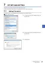
Страница 41: ...7 OFFSET GAIN SETTING 7 1 Setting Procedure 39 7 13 Click Yes button ...
Страница 47: ...I 45 MEMO ...
Страница 51: ......


