background image

2

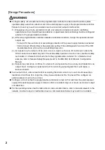
[Design Precautions]

WARNING

Configure safety circuits external to the programmable controller to ensure that the entire system 
operates safely even when a fault occurs in the external power supply or the programmable controller. 
Failure to do so may result in an accident due to an incorrect output or malfunction.
(1) Emergency stop circuits, protection circuits, and protective interlock circuits for conflicting 

operations (such as forward/reverse rotations or upper/lower limit positioning) must be configured 
external to the programmable controller.

(2) When the programmable controller detects an abnormal condition, it stops the operation and all 

outputs are:
 • Turned off if the overcurrent or overvoltage protection of the power supply module is activated.
 • Held or turned off according to the parameter setting if the self-diagnostic function of the CPU 

module detects an error such as a watchdog timer error.

(3) All outputs may be turned on if an error occurs in a part, such as an I/O control part, where the 

CPU module cannot detect any error. To ensure safety operation in such a case, provide a safety 
mechanism or a fail-safe circuit external to the programmable controller. For a fail-safe circuit 
example, refer to "General Safety Requirements" in the MELSEC iQ-R Module Configuration 
Manual.

(4) Outputs may remain on or off due to a failure of a component such as a relay and transistor in an 

output circuit. Configure an external circuit for monitoring output signals that could cause a 
serious accident.

In an output circuit, when a load current exceeding the rated current or an overcurrent caused by a 
load short-circuit flows for a long time, it may cause smoke and fire. To prevent this, configure an 
external safety circuit, such as a fuse.

Configure a circuit so that the programmable controller is turned on first and then the external power 
supply. If the external power supply is turned on first, an accident may occur due to an incorrect output 
or malfunction.

For the operating status of each station after a communication failure, refer to manuals relevant to the 
network. Incorrect output or malfunction due to a communication failure may result in an accident.

Содержание R60RD8-G

Страница 1: ...MELSEC iQ R Channel Isolated Thermocouple Input Module Channel Isolated RTD Input Module User s Manual Startup R60TD8 G R60RD8 G ...

Страница 2: ......

Страница 3: ...he safety precautions are classified into two levels WARNING and CAUTION Under some circumstances failure to observe the precautions given under CAUTION may lead to serious consequences Observe the precautions of both levels because they are important for personal and system safety Make sure that the end users read this manual and then keep the manual in a safe place for future reference WARNING I...

Страница 4: ...O control part where the CPU module cannot detect any error To ensure safety operation in such a case provide a safety mechanism or a fail safe circuit external to the programmable controller For a fail safe circuit example refer to General Safety Requirements in the MELSEC iQ R Module Configuration Manual 4 Outputs may remain on or off due to a failure of a component such as a relay and transisto...

Страница 5: ...aken between the external device and CPU module in case of a communication failure Do not write any data to the system area and write protect area of the buffer memory in the module Also do not use any use prohibited signals as an output signal from the CPU module to each module Doing so may cause malfunction of the programmable controller system For the system area write protect area and the use ...

Страница 6: ...afely regardless of the time Do not power off the programmable controller or reset the CPU module while the settings are being written Doing so will make the data in the flash ROM undefined The values need to be set in the buffer memory and written to the flash ROM again Doing so also may cause malfunction or failure of the module When changing the operating status of the CPU module from external ...

Страница 7: ...unction When using an extension cable connect it to the extension cable connector of the base unit securely Check the connection for looseness Poor contact may cause malfunction When using an SD memory card fully insert it into the SD memory card slot Check that it is inserted completely Poor contact may cause malfunction Securely insert an extended SRAM cassette into the cassette connector of the...

Страница 8: ...thin the specified torque range Undertightening can cause drop of the screw short circuit fire or malfunction Overtightening can damage the screw and or module resulting in drop short circuit fire or malfunction When disconnecting the cable from the module do not pull the cable by the cable part For the cable with connector hold the connector part of the cable For the cable connected to the termin...

Страница 9: ...rt circuit solder or throw the battery into the fire Also do not expose it to liquid or strong shock Doing so will cause the battery to produce heat explode ignite or leak resulting in injury and fire Shut off the external power supply all phases used in the system before cleaning the module or retightening the terminal screws connector screws or module fixing screws Failure to do so may result in...

Страница 10: ...malfunction Tighten the screws within the specified torque range Undertightening can cause drop of the component or wire short circuit or malfunction Overtightening can damage the screw and or module resulting in drop short circuit or malfunction After the first use of the product do not mount remove the module to from the base unit and the terminal block to from the module and do not insert remov...

Страница 11: ...n to the flash ROM again Doing so can cause malfunction or failure of the module CAUTION When disposing of this product treat it as industrial waste When disposing of batteries separate them from other wastes according to the local regulations For details on battery regulations in EU member states refer to the MELSEC iQ R Module Configuration Manual CAUTION When transporting lithium batteries foll...

Страница 12: ...Y INCLUDING BUT NOT LIMITED TO ANY AND ALL RESPONSIBILITY OR LIABILITY BASED ON CONTRACT WARRANTY TORT PRODUCT LIABILITY FOR ANY INJURY OR DEATH TO PERSONS OR LOSS OR DAMAGE TO PROPERTY CAUSED BY the PRODUCT THAT ARE OPERATED OR USED IN APPLICATION NOT INTENDED OR EXCLUDED BY INSTRUCTIONS PRECAUTIONS OR WARNING CONTAINED IN MITSUBISHI S USER INSTRUCTION AND OR SAFETY MANUALS TECHNICAL BULLETINS AN...

Страница 13: ...ne of the following manuals MELSEC iQ R Module Configuration Manual Safety Guidelines This manual is included with the base unit The CE mark on the side of the programmable controller indicates compliance with EMC and Low Voltage Directives Additional measures To ensure that this product maintains EMC and Low Voltage Directives please refer to one of the following manuals MELSEC iQ R Module Config...

Страница 14: ...12 MEMO ...

Страница 15: ...RE OPERATION 21 CHAPTER 5 WIRING 23 5 1 Wiring Precautions 23 Connector for external devices 23 5 2 External Wiring 24 Signal layout of connectors for external devices 24 External wiring examples 26 To use a connector terminal block converter module 29 CHAPTER 6 OPERATION EXAMPLES 31 6 1 Programming Procedure 31 6 2 Program Examples 31 CHAPTER 7 OFFSET GAIN SETTING 37 7 1 Setting Procedure 37 APPE...

Страница 16: ...arameter settings I O signals buffer memory and troubleshooting of the channel isolated thermocouple input module and the channel isolated RTD input module Print book e Manual PDF MELSEC iQ R Programming Manual Instructions Standard Functions Function Blocks SH 081266ENG Instructions for the CPU module dedicated instructions for the intelligent function modules and standard functions function bloc...

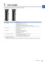
Страница 17: ...ff 5V power supply interrupted or watchdog timer error occurred module change for online module change possible 2 ERR LED Indicates the error status of the module On Error occurred 1 Off Normal operation 3 ALM LED Indicates the alarm status of the module On Alert process alarm or rate alarm issued Flashing Disconnection detected Off Normal operation 4 Connector for external devices A connector for...

Страница 18: ...16 1 PART NAMES MEMO ...

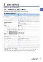
Страница 19: ...n accuracy and effect per wiring resistance 1Ω Cold junction compensation accuracy 1 0 Accuracy 1 For details refer to the following Page 40 Accuracy of the thermocouple input module Resolution B R S N 0 3 K E J T 0 1 Conversion speed 2 30ms channel Isolation method 3 Between thermocouple input channel and programmable controller power supply Transformer isolation Between thermocouple input channe...

Страница 20: ...nt temperature 25 5 1 1 ambient temperature 0 to 55 0 to 200 0 4 ambient temperature 25 5 1 2 ambient temperature 0 to 55 JPt100 180 to 600 0 8 ambient temperature 25 5 2 4 ambient temperature 0 to 55 20 to 120 0 3 ambient temperature 25 5 1 1 ambient temperature 0 to 55 0 to 200 0 4 ambient temperature 25 5 1 2 ambient temperature 0 to 55 Ni100 60 to 250 0 4 ambient temperature 25 5 1 2 ambient t...

Страница 21: ...ry area Scaling function Performs scale conversion from a measured temperature value to a value calculated using the ratio of the set scaling width to the set scaling range The converted value is stored in the buffer memory area Alert output function Process alarm Outputs an alert when a measured temperature value enters the preset alert output range Rate alarm Outputs an alert when the change of ...

Страница 22: ...er to the following MELSEC iQ R Online Module Change Manual Q compatible mode function Allows to convert the layout of buffer memory addresses of a temperature input module to the one equivalent to a MELSEC Q series module This compatibility enables the reuse of programs that have proven performance on MELSEC Q series modules Item Description ...

Страница 23: ... a module configuration by using the engineering tool For details refer to the following GX Works3 Operating Manual 4 Module settings Set up the parameters of the temperature input module by using the engineering tool For details refer to the following MELSEC iQ R Channel Isolated Thermocouple Input Module Channel Isolated RTD Input Module User s Manual Application 5 Offset gain setting Perform th...

Страница 24: ...22 4 PROCEDURES BEFORE OPERATION MEMO ...

Страница 25: ...ccording to the current value used The A6CON3 IDC type connector straight type cannot be used A connector terminal block converter module for MELSEC Q series temperature input module and the dedicated cable can be used For details refer to the following Page 29 To use a connector terminal block converter module 40 pin connector crimping tool For how to wire the connector and how to use the crimpin...

Страница 26: ...from the front of the module CH1 to CH8 RTD Pin number Signal name Pin number Signal name A1 CH1 B1 CH1 A2 B2 A3 CH2 B3 CH2 A4 B4 A5 CH3 B5 CH3 A6 B6 A7 CH4 B7 CH4 A8 B8 A9 CH5 B9 CH5 A10 B10 A11 CH6 B11 CH6 A12 B12 A13 CH7 B13 CH7 A14 B14 A15 CH8 B15 CH8 A16 B16 A17 B17 A18 B18 A19 B19 RTD A20 RTDG B20 RTD B20 B19 B18 B17 B16 B15 B14 B13 B12 B11 B10 B9 B8 B7 B6 B5 B4 B3 B2 B1 A20 A19 A18 A17 A16 ...

Страница 27: ...4 CH2 A2 B4 CH2 B2 A5 B5 A6 CH3 A3 B6 CH3 B3 A7 CH3 b3 B7 A8 B8 CH4 b4 A9 CH4 A4 B9 CH4 B4 A10 B10 A11 CH5 A5 B11 CH5 B5 A12 CH5 b5 B12 A13 B13 CH6 b6 A14 CH6 A6 B14 CH6 B6 A15 B15 A16 CH7 A7 B16 CH7 B7 A17 CH7 b7 B17 A18 B18 CH8 b8 A19 CH8 A8 B19 CH8 B8 A20 B20 B20 B19 B18 B17 B16 B15 B14 B13 B12 B11 B10 B9 B8 B7 B6 B5 B4 B3 B2 B1 A20 A19 A18 A17 A16 A15 A14 A13 A12 A11 A10 A9 A8 A7 A6 A5 A4 A3 A...

Страница 28: ...ocouple input module using an external device connector 1 Use a shielded cable and ground the shields Do not use a compensation lead wire 2 Use a shielded compensation lead wire and ground the shield Do not use a cable 3 Connect the cold junction compensation resistor RTD when With cold junction compensation 0 is set to Cold junction compensation with without setting Un G298 4 When connect the col...

Страница 29: ...Case 1 a cable is connected between the reference junction of the thermocouple and the relay terminal block Case 2 a compensation lead wire is connected between the relay terminal block and the thermocouple input module A B RTD Reference junction Compensation lead wire OK Cable NG Cable Ambient temperature difference Relay terminal block Thermocouple input module A Reference junction of the thermo...

Страница 30: ...d When connecting a resistance temperature detector to the RTD input module make sure that the conductor resistance values of three wires satisfy the conditions below Each conductor resistance of and must be 350 or lower The difference of conductor resistance values between and must be 10 or lower when Pt100 JPt100 or Ni100 is used 5 or lower when Pt50 is used CH1 A B b CH8 A B b CH1 A B b CH8 A B...

Страница 31: ...nction compensation with without setting Un G298 2 Ground the shields 3 The RTD and RTDG are connected in the connector terminal block converter module Therefore the connection of RTD and RTDG at the terminal block is not required Product name Model Remarks Contact Connector terminal block converter module FA LTB40TDG Your local Mitsubishi Electric sales office or representative Dedicated cable FA...

Страница 32: ... terminal block converter module FA LTB40RD3G Your local Mitsubishi Electric sales office or representative Dedicated cable FA CBL05Q68RD3G Cable length 0 5m FA CBL10Q68RD3G Cable length 1 0m FA CBL20Q68RD3G Cable length 2 0m FA CBL30Q68RD3G Cable length 3 0m RTD input module Dedicated cable Connector terminal block converter module CH1 A1 terminal 1 CH1 B1 terminal 2 Shield 1 Shield 1 Shield 1 CH...

Страница 33: ...dure Take the following steps to create a program for running a temperature input module 1 Set parameters Page 32 Parameter settings 2 Create a program Page 35 Program examples 6 2 Program Examples System configuration The following figure shows an example of the system configuration 1 Power supply module R61P 2 CPU module R120CPU 3 Temperature input module R60TD8 G 4 Input module RX10 1 2 3 4 ...

Страница 34: ...eter of the engineering tool The refresh settings do not need to be changed here For details on the module parameter refer to the following MELSEC iQ R Channel Isolated Thermocouple Input Module Channel Isolated RTD Input Module User s Manual Application Basic setting Configure the basic setting as shown below ...

Страница 35: ...6 OPERATION EXAMPLES 6 2 Program Examples 33 6 Application setting Configure the application setting as shown below ...

Страница 36: ...lue R60TDG_1 uConversionCompletedFlag 0 CH1 Conversion completed flag R60TDG_1 stnMonitor 2 wMeasuredTemperatureValue CH3 Measured temperature value R60TDG_1 uConversionCompletedFlag 2 CH3 Conversion completed flag R60TDG_1 stnMonitor 4 wMeasuredTemperatureValue CH5 Measured temperature value R60TDG_1 uConversionCompletedFlag 4 CH5 Conversion completed flag R60TDG_1 stnMonitor 6 wMeasuredTemperatu...

Страница 37: ...sing at the time of the issuance of a rate alarm upper lower limit alert in CH1 0 CH1 Measured temperature value CH3 Measured temperature value CH5 Scaling value and CH7 Measured temperature value are to be read 0 At the time when a process alarm upper limit alert is issued in CH3 the processing is to be performed 43 At the time when a process alarm lower limit alert is issued in CH3 the processin...

Страница 38: ...gram example 5 This program is an example to make the latest error code appear when disconnection is detected or an error has occurred After this the program clears the disconnection detection flag error flag and stored error code 0 At the time when disconnection is detected in CH7 the processing is to be performed 0 Error manipulation start flag is to be turned on ...

Страница 39: ...etting window in the engineering tool to set the offset and gain values 7 1 Setting Procedure The setting procedure for the offset gain setting of a temperature input module is as follows Tool Module Tool List 1 In Temperature Input select Offset gain setting and click OK button 2 Select the target module for the offset gain setting and click OK button 3 Click Yes button ...

Страница 40: ...lue that becomes an offset value to the terminal of the corresponding channel and click Yes button 8 Check that Offset Status has changed to Changed 9 Write the temperature setting value corresponding to the gain value to Gain Temperature Setting Value 10 Click Gain Setting button 11 Apply a value that becomes a gain value to the terminal of the corresponding channel and click Yes button 12 Check ...

Страница 41: ...7 OFFSET GAIN SETTING 7 1 Setting Procedure 39 7 13 Click Yes button ...

Страница 42: ...ompensation accuracy Usable thermocouple Temperature measuring range 1 Conversion accuracy for operating ambient temperature 25 5 Temperature characteristics for 1 of operating ambient temperature change Maximum temperature error at ambient temperature 55 Effect per wiring resistance 1 4 B 0 to 600 3 3 3 3 600 to 800 2 1 3 0 3 8 8 0 042 800 to 1700 2 1 0 0 29 8 25 0 036 1700 to 1820 3 3 3 3 R 50 t...

Страница 43: ...lue with the offset gain setting J 210 to 40 3 3 3 3 40 to 750 2 0 2 0 06 or a larger value of 0 02 or 0 02 of measured temperature 3 95 0 006 750 to 1200 3 3 3 3 T 270 to 200 3 3 3 3 200 to 0 2 0 5 0 06 or a larger value of 0 1 or 0 1 of measured temperature 5 5 0 016 0 to 350 2 0 4 0 06 or a larger value of 0 02 or 0 02 of measured temperature 2 15 0 007 350 to 400 3 3 3 3 N 270 to 200 3 3 3 3 2...

Страница 44: ... 1604 1997 IEC 751 1983 Allowance of JPt100 and Pt50 JIS C 1604 1981 Allowance of Ni100 DIN 43760 1987 AC Conversion accuracy ALRTD Allowance of the resistance temperature detector used Class Allowance A 0 15 0 002 t B 0 3 0 005 t Class Allowance 0 15 0 15 0 0015 t 0 2 0 15 0 002 t 0 5 0 3 0 005 t Class Allowance 0 to 250 0 4 0 007 t 60 to 0 0 4 0 0028 t ...

Страница 45: ...APPENDICES Appendix 2 External Dimensions 43 A Appendix 2 External Dimensions The following figure shows the external dimensions of a temperature input module Unit mm 98 4 106 110 27 8 ...

Страница 46: ...or for external devices 15 23 E ERR LED 15 External dimensions 43 External wiring examples 26 O Offset gain setting 37 P Performance specifications 17 Production information marking 15 Program examples 31 R RTD input module 14 RUN LED 15 S Signal layout of connectors for external devices 24 T Temperature input module 14 Thermocouple input module 14 ...

Страница 47: ...I 45 MEMO ...

Страница 48: ...93ENG B Added or modified parts RELEVANT MANUALS Chapter 4 Section 5 2 7 1 Appendix 1 2 August 2020 SH NA 081493ENG C Added or modified part Appendix 2 This manual confers no industrial property rights or any rights of any other kind nor does it confer any patent licenses Mitsubishi Electric Corporation cannot be held responsible for any problems involving industrial property rights which may occu...

Страница 49: ...been avoided if functions or structures judged as necessary in the legal safety measures the user s device is subject to or as necessary by industry standards had been provided 4 Failure that could have been avoided if consumable parts battery backlight fuse etc designated in the instruction manual had been correctly serviced or replaced 5 Failure caused by external irresistible forces such as fir...

Страница 50: ...mes system names and product names mentioned in this manual are either registered trademarks or trademarks of their respective companies In some cases trademark symbols such as or are not specified in this manual SH NA 081493ENG C ...

Страница 51: ......
Страница 52: ...nge without notice When exported from Japan this manual does not require application to the Ministry of Economy Trade and Industry for service transaction permission HEAD OFFICE TOKYO BUILDING 2 7 3 MARUNOUCHI CHIYODA KU TOKYO 100 8310 JAPAN NAGOYA WORKS 1 14 YADA MINAMI 5 CHOME HIGASHI KU NAGOYA JAPAN ...

Отзывы: