


16
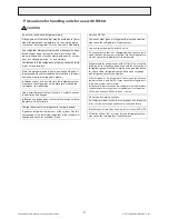
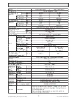
Specifications are subject to change without notice.
© 2017 Mitsubishi Electric US, Inc.
7 REFRIGERANT SYSTEM DIAGRAM
PVFY-P12,18, 24, 30, 36, 48, 54NAMU-E1
(H)
(I)
(F)
(E)
(E)
(C)
(G)
(A)
(D)
(B)
(A)
Gas pipe thermistor TH23
(B)
Gas pipe
(C)
Liquid pipe
(D)
Brazed connections
(E)
Strainer (#100 mesh)
(F)
Linear expansion valve
(G)
Liquid pipe thermistor TH22
(H)
Heat exchanger
(I)
Room temperature thermistor TH21
Capacity
PVFY-P12, 18NAMU-E1
PVFY-P24, 30, 36, 48, 54NAMU-E1
Gas pipe
ø12.7 [1/2]
ø15.88 [5/8]
Liquid pipe
ø6.35 [1/4]
ø9.52 [3/8]
Содержание PVFY-P12 NAMU-E
Страница 2: ......


