3
4
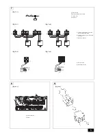
[Fig. 4.2.1]
A
Controller
B
Screw (field supply)
6
[Fig. 6.2.1]
A
Remove the cap
[Fig. 6.2.2]
[Fig. 6.2.3]
A
Heat exchanger (field supply)
B
LEV-kit
C
Brazing
D
Linear expansion valve
E
Outdoor unit
F
Refrigerant pipe size ø9.52 (field supply)
G
Distributor (field supply)
H
Refrigerant pipe size ø9.52 (field supply)
[Fig. 6.2.4]
A
Heat exchanger (field supply)
B
LEV-kit
C
Brazing
D
Linear expansion valve
E
Outdoor unit
F
Refrigerant pipe size ø9.52 (field supply)
G
Distributor (field supply)
H
Refrigerant pipe size ø9.52 (field supply)
I
Refrigerant pipe size
P400: ø12.7 (field supply)
P500: ø15.88 (field supply)
[Fig. 6.3.0.1]
[Fig. 6.3.0.2]
B
A
400
274
A
B
A
D
C
C
E
A
Heat exchanger (field supply)
B
LEV-kit
C
Brazing
D
Linear expansion valve
E
Outdoor unit
Type 125 - 140
G
G
H
H
C
F
C F
D
E
A
B
B
Type 250
G
I
H
A
G
G
F C
D
C F
C F
F C
D
H
G
I
G
G
E
B
B
Type 500
A
B
A
Most sensitive point of the thermistor
B
Maximize the contact


