9
GB
4. Selecting an installation site and installing the controller
•
Avoid locations in direct sunlight.
•
Avoid locations exposed to outside air.
•
Avoid locations exposed to the elements or water splashes.
•
Avoid locations exposed to stream or oil vapour.
•
Avoid locations where combustible gas may leak, settle or be generated.
•
Avoid installation near machines emitting high-frequency waves.
•
Avoid places where acidic solutions are frequently handled.
•
Avoid places where sulphur-based or other sprays are frequently used.
4.1. Combining indoor units with outdoor
units
For combining indoor units with outdoor units, refer to the outdoor unit installation
manual.
4.2. Installing the controller
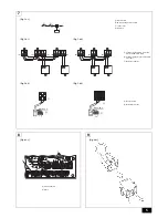
[Fig. 4.2.1] (P.3)
A
Controller
B
Screw (field supply)
When mounting the controller, use 4 supplied controller mounting screws, and
mount it vertically.
Warning:
Do not mount the horizontally laid controller.
5. Refrigerant pipe specifications
To avoid dew drops, provide sufficient antisweating and insulating work to the
refrigerant and drain pipes.
When using commercially available refrigerant pipes, be sure to wind commer-
cially available insulating material (with a heat-resisting temperature of more than
100
°C and thickness given below) onto both liquid and gas pipes.
Be also sure to wind commercially available insulating material (with a form poly-
ethylene’s specific gravity of 0.03 and thickness given below) onto all pipes which
pass through rooms.
1
Select the thickness of insulating material by pipe size.
2
If the unit is used on the highest story of a building and under conditions of
high temperature and humidity, it is necessary to use pipe size and insulating
material’s thickness more than those given in the table above.
3
If there are customer’s specifications, simply follow them.
6. Connecting refrigerant pipes
6.1. Refrigerant piping work
This piping work must be done in accordance with the installation manuals for
both outdoor unit and BC controller (simultaneous cooling and heating series
R2).
•
Series R2 is designed to operate in a system that the refrigerant pipe from an
outdoor unit is received by BC controller and branches at the BC controller to
connect between indoor units.
•
For constraints on pipe length and allowable difference of elevation, refer to
the outdoor unit manual.
Cautions On Refrigerant Piping
X
Be sure to use non-oxidative brazing for brazing to ensure that no for-
eign matter or moisture enter into the pipe.
X
Be sure to apply refrigerating machine oil over the flare connection
seating surface and tighten the connection using a double spanner.
X
Provide a metal brace to support the refrigerant pipe so that no load is
imparted to the indoor unit end pipe. This metal brace should be pro-
vided 50 cm away from the indoor unit’s flare connection.
Warning:
When installing and moving the unit, do not charge it with refrigerant other
than the refrigerant specified on the unit.
- Mixing of a different refrigerant, air, etc. may cause the refrigerant cycle to
malfunction and result in severe damage.
Caution:
•
Use refrigerant piping made of C1220 (CU-DHP) phosphorus deoxidized
copper as specified in the JIS H3300 “Copper and copper alloy seam-
less pipes and tubes”. In addition, be sure that the inner and outer sur-
faces of the pipes are clean and free of hazardous sulphur, oxides, dust/
dirt, shaving particles, oils, moisture, or any other contaminant.
•
Never use existing refrigerant piping.
- The large amount of chlorine in conventional refrigerant and refrigerator oil
in the existing piping will cause the new refrigerant to deteriorate.
•
Store the piping to be used during installation indoors and keep both
ends of the piping sealed until just before brazing.
- If dust, dirt, or water gets into the refrigerant cycle, the oil will deteriorate
and the compressor may fail.
•
Use Suniso 4GS or 3GS (small amount) refrigerator oil to coat the flare
and flange connection part. (For models using R22)
•
Use ester oil, ether oil or alkylbenzene (small amount) as the refrigera-
tor oil to coat flares and flange connections. (For models using R410A
or R407C)
- The refrigerant used in the unit is highly hygroscopic and mixes with water
and will degrade the refrigerator oil.
6.2. Liner expansion valve piping work
Attach the supplied LEV-kit to the liquid pipe of the heat exchanger (field supply).
For Type250, connect two LEV-kits. For Type500, connect four LEV-kits.
[Fig. 6.2.1] (P.3)
A
Remove the cap
[Fig. 6.2.2] (P.3)
A
Heat exchanger (field supply)
B
LEV-kit
C
Brazing
D
Linear expansion valve
E
Outdoor unit
[Fig. 6.2.3] (P.3)
A
Heat exchanger (field supply)
B
LEV-kit
C
Brazing
D
Linear expansion valve
E
Outdoor unit
F
Refrigerant pipe size ø9.52 (field supply)
G
Distributor (field supply)
H
Refrigerant pipe size ø9.52 (field supply)
[Fig. 6.2.4] (P.3)
A
Heat exchanger (field supply)
B
LEV-kit
C
Brazing
D
Linear expansion valve
E
Outdoor unit
F
Refrigerant pipe size ø9.52 (field supply)
G
Distributor (field supply)
H
Refrigerant pipe size ø9.52 (field supply)
I
Refrigerant pipe size
P400: ø12.7 (field supply)
P500: ø15.88 (field supply)
Caution:
Install the LEV-kit inside the AHU, and keep it away from rain or direct sun-
light.
Caution:
Install the LEV-kit with its motor upward.
6.3. Thermistor setting work
Caution:
The evaporator and the thermistor must touch each other. The top of the
most sensitive part of the thermistor must touch the evaporator.
[Fig. 6.3.0.1] (P.3)
A
Most sensitive point of the thermistor
B
Maximize the contact
Caution:
Put the thermistor wire slightly down to avoid water accumulation on top of
the thermistor.
[Fig. 6.3.0.2] (P.3)
Pipe size
Insulating material’s thickness
6.4 mm to 25.4 mm
More than 10 mm
28.6 mm to 38.1 mm
More than 15 mm


