


3. SIGNALS AND WIRING
3 - 17
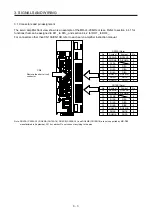
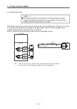
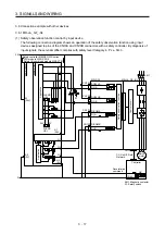
3.8 Connection example with other devices
3.8.1 MR-J4-_GF_-RJ
(1) Safety observation function control by input device
The following connection diagram shows an operation of the safety observation function using input
devices assigned to pins of the CN10A and CN10B connectors with a safety controller. By diagnosis of
input signals, the servo amplifier complies with safety level Category 4, PL e, SIL 3.
A1
(24V)
A2
(0V)
24 V
0 V
FLEXB
US+
FLEXB
US+
24 V
0 V
X1
X2
A1
(24V)
Q1
Q2
Q3
A2
(0V)
WS0-CPU0
WS0-XTIO
CN10A
CN10B
S1
CN10A
CN10B
DO24VA
DO24VB
DO_A
DO_B
DICOMA
DI_A
DICOMB
DI_B
CN1A
CC-Link IE Field
Network
Controller
MR-D30
MR-J4-_GF_-RJ
KM1
QX_
COM
I1
I2
I3
I4
Servo
motor
Deceleration
command
KM1: Magnetic contactor
S1: Safety switch
Application
Application
Control circuit
Safety observation function
Safety controller MELSEC-WS series
CPU module WSO-CPU0
Safety I/O combined module WS0-XTIO
Содержание MR-D30
Страница 13: ...4 MEMO ...
Страница 41: ...1 FUNCTIONS AND CONFIGURATION 1 28 MEMO ...
Страница 141: ...6 DISPLAY 6 2 MEMO ...
Страница 153: ...MEMO ...