


3. SIGNALS AND WIRING
3 - 9
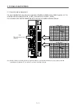
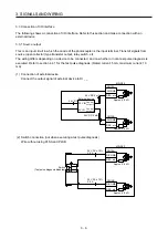
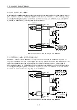
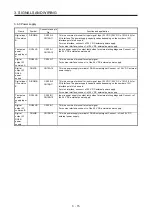
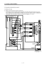
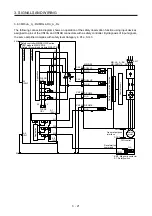
3.3.3 DO1_ to DO3_ source output
When the output transistor is turned on, the current will flow to the output terminal to a load. A lamp, relay, or
photocoupler can be driven. Install a diode (D) for an inductive load, or install an inrush current suppressing
resistor (R) for a lamp load. (Rated current: 5 mA to 40 mA, maximum current: 50 mA, inrush current: 100
mA or less) A maximum of 2.4 V voltage drop occurs in MR-D30.
MR-D30
CN10A
DO24VB
DO1B to
DO3B
CN10B 24 V DC ± 10%
0.8 A
24 V DC ± 10%
0.8 A
DO24VA
DO1A to
DO3A
Load
(Note)
(Note)
Load
Safety relay
If polarity of diode is
reversed, MR-D30
will malfunction.
If polarity of diode is
reversed, MR-D30
will malfunction.
Note. If polarity of power is reversed, the safety relay may malfunction.
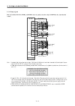
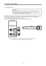
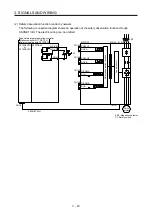
3.3.4 DO4NA source output and DO4NB sink output
DO4NA as source output and DO4PB as sink output can be combined to use. As for DO4NA, when the
output transistor is turned on, the current will flow from the output terminal to a load. As for DO4PB, when the
output transistor is turned on, the current will flow from a load to the output terminal. A lamp, relay, or
photocoupler can be driven. Install a diode (D) for an inductive load, or install an inrush current suppressing
resistor (R) for a lamp load. (Rated current: 5 mA to 40 mA, maximum current: 50 mA, inrush current: 100
mA or less) A maximum of 2.4 V voltage drop occurs in MR-D30.
MR-D30
CN10A
DO4PB
DO4NB
CN10B
24 V DC ± 10%
0.8 A
24 V DC ± 10%
0.8 A
DO4PA
DO4NA
Load
Load
Safety relay
If polarity of diode is
reversed, MR-D30
will malfunction.
If polarity of diode is
reversed, MR-D30
will malfunction.
(Note)
(Note)
Note. If polarity of power is reversed, the safety relay may malfunction.
Содержание MR-D30
Страница 13: ...4 MEMO ...
Страница 41: ...1 FUNCTIONS AND CONFIGURATION 1 28 MEMO ...
Страница 141: ...6 DISPLAY 6 2 MEMO ...
Страница 153: ...MEMO ...