
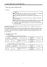


1. FUNCTIONS AND CONFIGURATION
1 - 11
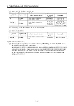
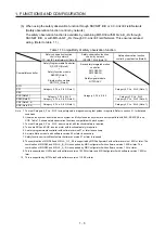
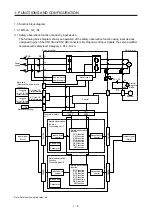
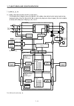
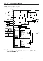
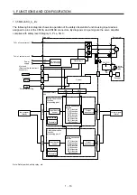
1.3.4 MR-J4-DU_B_-RJ
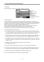
(1) Safety observation function control by input device
The following block diagram shows an operation of the safety observation function using input devices
assigned to pins of the CN10A and CN10B connectors. By diagnosis of input signals, the servo amplifier
complies with safety level Category 4, PL e, SIL 3.
To L+ of converter unit
L+
L-
L11
L21
M
U
V
W
U
V
W
24 V DC
B1
B2
B
RA
CN9
CN90
CN7
CN70
SSCNET III/H
SSCNET III/H
USB
CN8
CN1
A
CN1
B
CN5
CN2
C
N
10A
C
N
10B
C
N
10A
C
N
10B
Gate circuit
Safety observation
function
processing part 1
Servo motor
Drive unit
To L- of converter unit
Power
supply
Not used
(Remove the short-circuit
connector.)
Controller
or servo
amplifier
Servo
amplifier
Parameter setting
Control circuit
power supply
Encoder
Electro-
magnetic
brake
Control
Functional safety
unit
Input signal
(Note)
Input device
control
Self-check
Parameter
Safety observation
function
STO function
SS1 function
SS2 function
SOS function
SLS function
SSM function
SBC function
SM function
Safety observation
function
STO function
SS1 function
SS2 function
SOS function
SLS function
SSM function
SBC function
SM function
Safety observation
function
processing part 2
Input device
control
Self-check
Parameter
Output
device control
Output
device control
Output signal
(Note)
Note. Safety switch, safety relay, etc.
Содержание MR-D30
Страница 13: ...4 MEMO ...
Страница 41: ...1 FUNCTIONS AND CONFIGURATION 1 28 MEMO ...
Страница 141: ...6 DISPLAY 6 2 MEMO ...
Страница 153: ...MEMO ...