


62
5 SIGNALS AND WIRING
5.7 Interface
Source I/O interface
For the MR-CV_ power regeneration converter unit, source type I/O interfaces can be used.
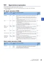
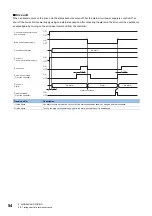
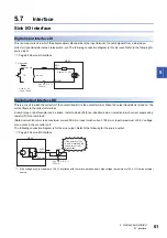
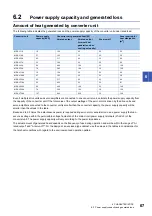
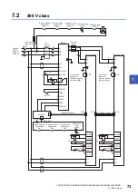
Digital input interface DI
This is an input circuit in which the anode of the photocoupler is the input terminal. Transmit signals from a source (open-
collector) type transistor output, relay switch, etc.
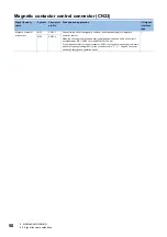
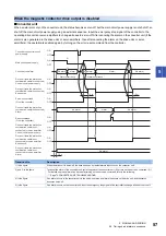
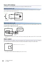
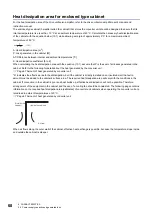
Digital output interface DO
This is a circuit in which the emitter of the output transistor is the output terminal. When the output transistor is turned on, the
current flows from the output terminal to a load.
A maximum of 2.6 V voltage drop occurs in the converter unit.
*1 If the voltage drop (a maximum of 2.6 V) interferes with the relay operation, apply high voltage (a maximum of 26.4 V) from an external
source.
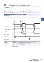
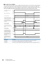
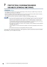
Alarm output
When the converter unit is operating normally, the line between B and C is closed. When an alarm occurs, the line between A
and C becomes closed. Connect the converter unit to the alarm output (A/B/C) via a relay coil or by other means.
*1 For compliance with the IEC/EN/UL/CSA standards, operate at 30 V DC or less.
TR
350 mA
EM1
DICOM
± 10 %
V
CES
≤
1.0 V
I
CEO
≤
100
μ
A
MR-CV_
For transistor
Approx. 5 mA
etc.
Approx. 4.1 k
Ω
Switch
24 V DC
ALM
DOCOM
350 mA
± 10 %
*1
MR-CV_
Load
etc.
24 V DC
If the polarity of the
diode is reversed, the
converter unit will
malfunction.
A
B
C
MR-CV_
Permissible load: 230 V AC 0.3 A, 30 V DC 0.3 A
*1
Содержание -MR-CV
Страница 1: ...MR CV Power Regeneration Converter Unit User s Manual MR CV_ Mitsubishi Electric AC Servo System ...
Страница 2: ......
Страница 19: ...3 FUNCTION BLOCK DIAGRAM 17 3 MEMO ...
Страница 119: ......


