


56
5 SIGNALS AND WIRING
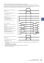
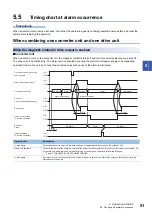
5.5 Timing chart at alarm occurrence
■
Drive unit
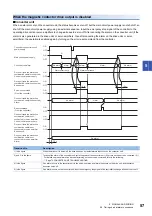
If an alarm occurs on the drive unit of the axis connected by the protection coordination cable, the base circuit is shut off, and
the servo motor begins to coast. If an alarm occurs on a drive unit or servo amplifier other than the axis connected by the
protection coordination cable, turn off the magnetic contactor using an external sequence and shut off the main circuit power
supply. Once the power supply is shut off, the dynamic brake is activated and the servo motor stops. If an alarm occurs on any
of the axes, input the emergency stop signal of the controller to change all axes to servo-off.
The alarm can be canceled by cycling the control circuit power supply, turning on the error reset command from the controller,
or using the CPU reset command, but it cannot be canceled unless the cause of the alarm is eliminated.
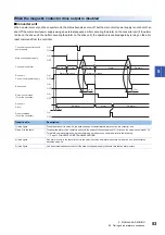
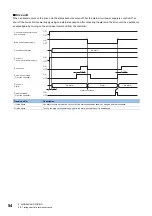
Transition No.
Description
1) in the figure
After the drive unit has started up, the main circuit power supply is turned on without alarms for the drive unit and converter
unit.
2) in the figure
If an alarm occurs on any of the axes, input the emergency stop signal of the controller to change all axes to servo-off.
ON
OFF
ON
OFF
ON
OFF
(3 s)
ON
OFF
1.5 s
(3 s)
ON
OFF
ON
OFF
2)
1)
1)
ON
OFF
ON
OFF
ON
OFF
Alarm
No alarm
No alarm
No alarm
Alarm occurrence
No alarm
Drive unit (axis the protection
coordination cable is connected)
Control circuit power supply
Main circuit power supply
Servo-on command
(From the controller)
Drive unit (axis the protection
coordination cable is connected)
Alarm
Drive unit (axis the protection
coordination cable is connected)
Base circuit
Reset command
(From the controller)
Drive unit (axis the protection
coordination cable is not
connected) or servo amplifier
Control circuit power supply
Drive unit (axis the protection
coordination cable is not
connected) or servo amplifier
Base circuit
Drive unit (axis the protection
coordination cable is not
connected) or servo amplifier
Alarm
Converter unit control circuit
power supply
Converter unit alarm
Содержание -MR-CV
Страница 1: ...MR CV Power Regeneration Converter Unit User s Manual MR CV_ Mitsubishi Electric AC Servo System ...
Страница 2: ......
Страница 19: ...3 FUNCTION BLOCK DIAGRAM 17 3 MEMO ...
Страница 119: ......


