


12
2 INSTALLATION
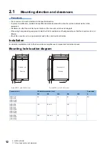
2.1 Mounting direction and clearances
2.1
Mounting direction and clearances
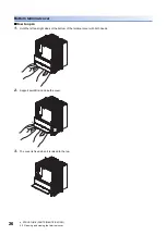
Precautions
• The converter unit must be installed in the specified direction.
• To prevent a malfunction, maintain the specified clearances between the converter unit and cabinet walls or other
equipment.
• Circulate air so that the air at the top and bottom of the converter unit does not stagnate.
• When using heat generating equipment, install it with full consideration of heat generation so that the converter unit is not
affected.
• Mount the converter unit on a perpendicular wall in the correct vertical direction.
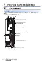
Installation
For details on installation, refer to the drive unit/servo amplifier user's manual and instruction manual.
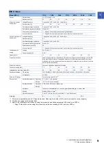
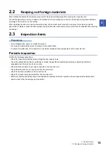
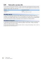
Mounting hole location diagram
Converter unit
Variable dimensions [mm]
Screw size
W1
W2
W3
W4
W5
A
MR-CV11K
MR-CV18K
MR-CV11K4
MR-CV18K4
90
45
82
4
M5
MR-CV30K
MR-CV37K
MR-CV45K
MR-CV30K4
MR-CV37K4
MR-CV45K4
150
60 ± 0.5
142
MR-CV55K
MR-CV55K4
MR-CV75K4
300
180 ± 0.5
60
282
9
380
360 ± 0.5
10
(10)
342
19
(19)
W1
W3
W2
W4
(W5)
(W3)
W5
380
360 ± 0.5
10
(10)
342
19
(19)
(W3)
W1
W3
W4
(W5)
W5
Converter unit
Converter unit
Opening
Opening
2-A screw
4-A screw
For the MR-CV_ with 18 kW or less
For the MR-CV_ with 30 kW or more
Содержание -MR-CV
Страница 1: ...MR CV Power Regeneration Converter Unit User s Manual MR CV_ Mitsubishi Electric AC Servo System ...
Страница 2: ......
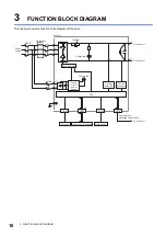
Страница 19: ...3 FUNCTION BLOCK DIAGRAM 17 3 MEMO ...
Страница 119: ......


