


30
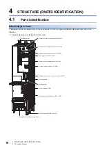
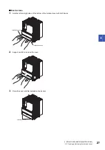
4 STRUCTURE (PARTS IDENTIFICATION)
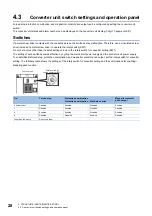
4.3 Converter unit switch settings and operation panel
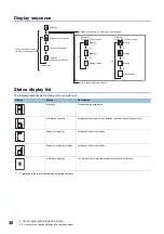
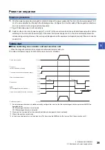
Display sequence
Status display list
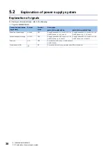
The following table shows the status of the converter unit.
*1 "*" represents the alarm numbers and warning numbers.
Display
Status
Description
Initializing
Displayed during initialization.
Initialization complete
Displayed when the status is initialization complete, ready-off, and servo-off.
Ready-off (charging)
Displayed in the servo-off status.
Ready-on (charging complete)
Displayed in the servo-on status.
Alarms and warnings
The alarm number or warning number that occurred is displayed.
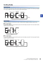
1.5 s
1 s
1.5 s
1 s
1 s
1 s
1 s
Example:
When [6E.1] has occurred
Example:
When [61] has occurred
When an alarm occurs,
its alarm code appears.
Initializing
Ready-off (charging)
Ready-on
(charging completed)
Forced stop
Blinking
Alarm reset or warning cleared
When an alarm No. or warning No. is displayed
Blinking
Displays blank
Blinking
Blinking
Blinking
Displays blank
Initialization completed
Содержание -MR-CV
Страница 1: ...MR CV Power Regeneration Converter Unit User s Manual MR CV_ Mitsubishi Electric AC Servo System ...
Страница 2: ......
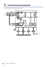
Страница 19: ...3 FUNCTION BLOCK DIAGRAM 17 3 MEMO ...
Страница 119: ......


