


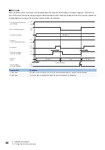


42
5 SIGNALS AND WIRING
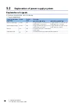
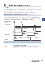
5.2 Explanation of power supply system
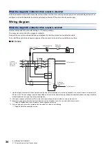
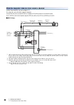
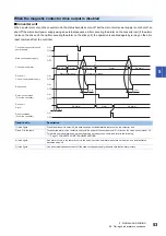
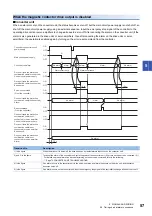
■
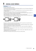
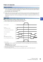
When connecting multiple drive units and servo amplifiers to the converter unit
• When the magnetic contactor drive output is enabled and remains ready-on
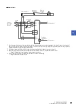
*1 If an electromagnetic brake is installed externally, configure the circuit so that the electromagnetic brake operates with MBR as
described below.
ON: Electromagnetic brake is not activated
OFF: Electromagnetic brake is activated
*2 Give a position command after the externally-installed electromagnetic brake is released.
*3 When in the position control mode.
*4 In the drive unit parameters, set the delay time (Tb) from when the MBR shuts off at servo-off until base circuit shut-off.
*5 The main circuit power supply is not shut off even in the servo-off status.
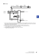
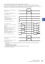
(95 ms)
(3 s)
*2
*2
Tb
*4
(3 s)
Tb
*5
OFF
ON
OFF
ON
OFF
ON
OFF
ON
OFF
ON
ON
OFF
OFF
ON
OFF
ON
ON
OFF
0 r/min
0 r/min
0 r/min
0 r/min
Drive unit (axis the protection coordination cable is
connected)
Servo motor speed
Drive unit (axis the protection coordination cable is
not connected) or servo amplifier
Servo motor speed
Main circuit power supply
Drive unit (axis the protection coordination cable is
connected)
Base circuit
Drive unit (axis the protection coordination cable is
not connected) or servo amplifier
Control circuit power supply
Drive unit (axis the protection coordination cable is
connected)
Control circuit power supply
Drive unit (axis the protection coordination cable is
connected)
MBR (Electromagnetic brake interlock)
*1
Drive unit (axis the protection coordination cable is
not connected) or servo amplifier
Base circuit
Drive unit (axis the protection coordination cable is
not connected) or servo amplifier
MBR (Electromagnetic brake interlock)
*1
Drive unit (axis the protection coordination cable is
connected)
Position command
*3
Drive unit (axis the protection coordination cable is
not connected) or servo amplifier
Position command
*3
Servo-on command (From the controller)
Converter unit control circuit power supply
Содержание -MR-CV
Страница 1: ...MR CV Power Regeneration Converter Unit User s Manual MR CV_ Mitsubishi Electric AC Servo System ...
Страница 2: ......
Страница 19: ...3 FUNCTION BLOCK DIAGRAM 17 3 MEMO ...
Страница 119: ......


