


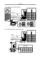
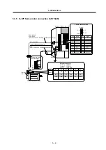
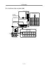
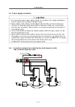


5. Connections
5
−
2
●
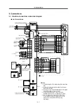
SJ-PF Series Motor
Detector
1 1
2 0
6
1 6
7
1 7
Plate
A1
B5
A2
B2
A3
B3
A5
P5
5G
MA
MA*
MB
MB*
SHD
A4
24G
MOH
MZ
MZ*
1
1 0
1 8
8
B4
5
1 5
P 5
5G
MA
MA*
MB
MB*
SD
5G
P5
MZ*
MZ
24G
MOH
C N 2
A6
B6
(Note 3)
Cable
clamp
SH21 cable or FCUA-R000 cable
CN
1A
Mitsubishi
CNC
M D S - B - S V J 2
CS1
0
CN
1A
CN
1B
(Note 1)
FAN
H
K
A
N
C
R
P5
5G
PA
PA*
PB
PB*
B PZ
PZ*
P
ENC
1 1
2 0
4
1 4
3
1 3
1
1 2
2
P 5
5G
PA
PB
SD
5G
P5
PZ*
PZ
1 0
PA*
PB*
C N 2
(
Note 3)
※
Full closed
Speed meter
V
0~10V
output
C N 3
1 0
1 1
P24
24G
MO1
5G
MO2
5G
SD
9
1
1 9
1
2m or less
1 4
MCON
Do not connect when using
external power.
5m or less
External power
magnetic switch
(Note 5)
Miscellaneous
output 1, 2
Load meter
V
MC
RA
8
DO1
1 8
DO2
L11
L21
C
D
P
Regenerative resistor
L1
L2
L3
U
V
W
Power supply
3-phase 200VAC
NFB
T E 1
T E 2
MC
Configure a sequence in which
MC is disconnected by alarms
and emergency stops.
SJ-PF
Series Motor
PE
PE
Class 3 grounding or higher
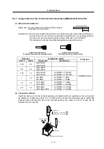
CS1
1
M D S - B - * *
CS1
2
CN1
A
CN
1
B
CS1
n-1
CN
1A
CN
1
B
CN
1B
SH21 cable or FCUA-R000 cable
SH21 cable or FCUA-R000 cable
Spindle amplifier
M D S - B - S P J 2
M D S - B - * *
U
V
W
I M
U
V
W
E
BU
BV
(BW)
L1
L2
(L3)
(L3)
L2
L1
E
FAN
(1st axis)
Plate
(nth axis)
(3rd axis)
Always insert a terminator (MDS-A-TM)
in CN1B at the end. (Note 4)
(Note 2)
Plate
The SH21 cable from the
previous axis is connected to the
CN1A connector.
(Notes)
1. The total length of the cable should be less than
30m.
2. The motor side connections after the 3rd axis
have been omitted.
3. Securely connect the shielded cable to the plate
(grounding plate) in the connector.
4. Connect an MDS-A-BT* when the servo
amplifier detector uses an absolute encoder.
5. Do not mistake the orientation of the diode.
The amplifier will fail and signals will not be
output if it is connected with the wrong
orientation.